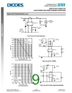
A Product Line of
Diodes Incorporated
ZXCT1107/1109/1110
LOW POWER HIGH-SIDE CURRENT MONITORS
Application Information (cont.)
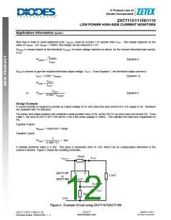
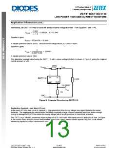
Alternatively, the ZXCT1110 may be used with a reduced sense voltage if desired. From Equation 3, with ε=4%,
0.082
VSENSE
=
= 0.082/(4-1.8) = 37.2mV
ε −1.8
Equation 4 gives
RSENSE = 37.2mV/2A = 18.6mΩ
A suitable preferred value is 20mꢀ. Then the sense voltage will be 2A * 20mꢀ = 40mV.
Equation 5 gives
2
RGAIN
=
= 12500ꢀ
0.004 * 0.04
A suitable preferred value is 13kꢀ.
The alternative example circuit using the ZXCT1110 with a sense voltage of 40mV is shown in Figure 3, giving the required
overall accuracy of ±6%.
20mΩ
ILOAD
VSUPPLY
S+
S-
ZXCT1110
LOAD
GND
OUT
OUTPUT
VOUT
13k
GND
Figure 3. Example Circuit using ZXCT1110
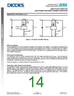
Protection Against Load Short Circuit
In the event of a load short circuit or overload, a large proportion of the supply voltage may appear between the sense
terminals. The supply may be current limited, but there is normally a large reservoir capacitor which can deliver enough
energy to damage the ZXCT11xx before the supply voltage falls to a safe level due to current limit activation.
The ZXCT11xx is rated for a maximum sense voltage of +0.8V, but is safe if the input current is limited to ±8.5mA. In Figure
4, the resistor RPROT limits the current and therefore protects the current monitor device against load short circuit without
introducing significant current measurement error.
13 of 17
www.diodes.com
MARCH 2011
© Diodes Incorporated
ZXCT1107/1109/1110
Document number: DS35033 Rev. 1 - 2

 DIODES [ DIODES INCORPORATED ]