A Product Line of
Diodes Incorporated
ZXCT1107/1109/1110
LOW POWER HIGH-SIDE CURRENT MONITORS
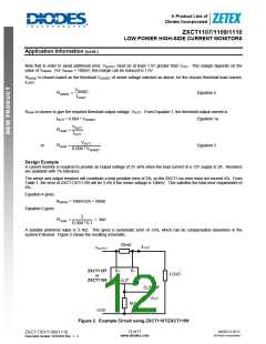
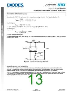
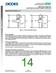
Application Information (cont.)
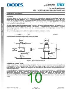
The ZXCT1110 is highly linear and has a transconductance of 4mA/V ±1.8% and an output of 40µA ±4µA at VSENSE=10mV.
The output current can therefore be calculated (Standard International Units) as:
IOUT = (40 +/-4)*10-6 + (VSENSE-0.01)*(0.004 +/- 0.000072) Amp
The worst-case current error is then
I
OUTERROR = IOUT – IOUTIDEAL = +/- { 4*10-6 + (VSENSE-0.01) * 0.000072 } Amp
or
I
OUTERROR = +/- { 3.28*10-6 + VSENSE * 0.000072 } A
The percentage error is
IOUTERROR
IOUTERROR
ε =
*100% =
*100%
IOUTIDEAL
VSENSE * 0.004
3.28 *10−4 + VSENSE * 0.0072
Then
or
%
ε = ±
ε = ±
VSENSE * 0.004
0.082
Equation 2
±1.8%
VSENSE
This shows that the error is reduced with increasing VSENSE. Then the minimum VSENSE required to give the error ±ε % is
0.082
VSENSE
=
V
[only for ZXCT1110]
Equation 3
ε −1.8
In the application, the effect of the external resistor tolerances must also be taken into account.
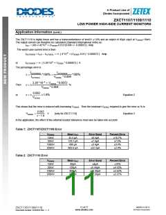
Table 1: ZXCT1107/ZXCT1109 Error
VSENSE
10mV
Mean IOUT
45.5 µA
Error Band
±8.5µA
Percent Error
±18.7%
±7.6%
±3.4%
±2.8%
30mV
124.5 µA
408 µA
±7.6µA
100mV
200mV
±3.4µA
809.8 µA
±22.5µA
Table 2: ZXCT1110 Error
VSENSE
10mV
Mean IOUT
40µA
Error Band
±4µA
Percent Error
±10%
30mV
120µA
400µA
800µA
±5.44µA
±10.48µA
±17.68µA
±4.53%
100mV
200mV
±2.62%
±2.21%
11 of 17
www.diodes.com
MARCH 2011
© Diodes Incorporated
ZXCT1107/1109/1110
Document number: DS35033 Rev. 1 - 2

 DIODES [ DIODES INCORPORATED ]