DA14580
FINAL
Bluetooth Low Energy 4.2 SoC
LDO groups in the system:
1. LDO RET: This is the LDO providing power to the
Retention domain (PD_AON). It powers the Retention
RAMs and the digital part which is always on.
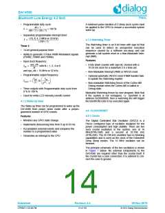
16 MHz
32.768 kHz
2. LDO OTP: This is the LDO powering the OTP macro
cell. This is the reason for using the step-up DC-DC
converter when running from an Alkaline battery.
3. LDO SYS: This is the LDO providing the system with
the actual VDD power required for the digital part to
operate. Note that the Power Block implements seam-
less switching from the LDO SYS to the LDO RET
when the system enters Deep Sleep mode. In the latter
case, a low voltage is applied to the PD_AON power
domain to further reduce leakage.
0-22.4 pF
clock16MHz
clock32kHz
4. LDO (various): This a group of LDOs used for the
elaborate control of the powering up/down of the
Radio, the GP ADC and the XTAL16M oscillator.
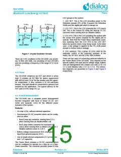
Figure 7: Crystal Oscillator Circuits
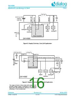
There are two ways of connecting external batteries to
the Power Block of the DA14580. They depend on the
specific battery cell used and its voltage range. Battery
cells are distinguished into Lithium coin cells (2.35 V to
3.3 V) and Alkaline cells (1.0 V to 1.8 V). The connec-
tion diagrams are presented in Figure 9 and Figure 8
respectively:
There are 3 RC oscillators in the DA14580: one provid-
ing 16 MHz (RC16M), one providing 32 kHz (RC32K)
and one providing a frequency in the range of 10.5 kHz
(RCX).
4.8.2 Reset
The DA14580 comprises an RST pad which is active
high. It contains an RC filter for spikes suppression
with 400 k and 2.8 pF for the resistor and the capaci-
tor respectively. It also contains a 25 k pull-down
resistor. This pad should be connected to ground if not
needed by the application. The typical latency of the
RST pad is in the range of 2 s.
4.9 POWER MANAGEMENT
The DA14580 has a complete power management
function integrated with Buck or Boost DC-DC con-
verter and separate LDOs for the different power
domains of the system.
Features
• On-chip LDOs, without external capacitors
• Synchronous DC-DC converter which can be config-
ured as either:
• Boost (step-up) converter, starting from 0.9 V,
when running from an Alkaline/NiMH cell.
• Buck (step-down) converter for increased effi-
ciency when running from a Lithium coin-cell or 2
Alkaline batteries down to 2.35 V.
• Battery voltage measurement ADC (multiplexed
input from general purpose ADC)
• Use of small external components (2.2 H inductor
and 1F capacitor)
The Power Block contains a DC-DC converter which
can be configured to operate as a Step-Up or a Step-
Down converter. The converter provides power to four
Datasheet
Revision 3.4
09-Nov-2016
CFR0011-120-00-FM
15 of 155
© 2014 Dialog Semiconductor

 DIALOG [ Dialog Semiconductor ]