DA14580
FINAL
A minimum pulse duration of 2 sleep clock cycles must
Bluetooth Low Energy 4.2 SoC
• Programmable duty cycle:
be applied to the GPIO to ensure a successful system
wake-up.
M + 1
M + 1 + N + 1
--------------------------------------------
=
100 %
• Separately programmable interrupt timer:
16, 8, 4, 2 MHz or 32 kHz
T = ------------------------------------------------------------------------
4.7.3 Watchdog Timer
ON + 1
The Watchdog timer is an 8-bit timer with sign bit that
can be used to detect an unexpected execution
sequence caused by a software run-away and can
generate a full system reset or a Non-Maskable Inter-
rupt (NMI).
Timer 2
• 14-bit general purpose timer
• Ability to generate 3 Pulse Width Modulated signals
(PWM2, PWM3 and PWM4)
Features
• Input clock frequency:
sys_clk
• 8 bits down counter with sign bit, clocked with a
10.24 ms clock for a maximum 2.6 s time-out.
fIN = ------------------- with N = 1, 2, 4 or 8
N
and sys_clk = 16 MHz or 32 kHz
• Non-Maskable Interrupt (NMI) or WDOG reset.
• Programmable output frequency:
• Optional automatic WDOG reset if NMI handler fails
to update the Watchdog register.
fIN
------
2
fIN
-----------------
2
fOUT
=
to
14
• Non-maskable Watchdog freeze of the Cortex-M0
Debug module when the Cortex-M0 is halted in
Debug state.
– 1
• Three outputs with Programmable duty cycle from
0 % to 100 %
Maskable Watchdog freeze by user program. Note that
if the system is not remapped, i.e. SysRAM is at
address 0x20000000, then a watchdog fire will trigger
the BootROM code to be executed again.
• Used for white LED intensity (on/off) control
4.7.2 Wake-Up timer
The Wake-up timer can be programmed to wake up the
DA14580 from power down mode after a prepro-
grammed number of GPIO events.
4.8 CLOCK/RESET
4.8.1 Clocks
Features
• Monitors any GPIO state change
• Implements debouncing time from 0 up to 63 ms
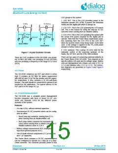
The Digital Controlled Xtal Oscillator (DXCO) is a
Pierce configured type of oscillator designed for low
power consumption and high stability. There are two
such crystal oscillators in the system, one at 16
• Accumulates external events and compares the
number to a programmed value
MHz(XTAL16M) and
a
second at 32.768 kHz
(XTAL32K). The 32.768 kHz oscillator has no trimming
capabilities and is used as the clock of the Extended/
Deep Sleep modes. The 16 MHz oscillator can be
trimmed.
• Generates an interrupt to the CPU
The principle schematic of the two oscillators is shown
in Figure 7 below. No external components to the
DA14580 are required other than the crystal itself. If
the crystal has a case connection, it is advised to con-
nect the case to ground.
Datasheet
Revision 3.4
09-Nov-2016
CFR0011-120-00-FM
14 of 155
© 2014 Dialog Semiconductor

 DIALOG [ Dialog Semiconductor ]