DA14580
FINAL
Bluetooth Low Energy 4.2 SoC
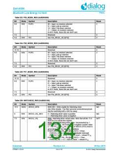
Table 233: P35_MODE_REG (0x50003090)
Bit
Mode Symbol
Description
Reset
9:8
R/W
PUPD
00 = Input, no resistors selected
01 = Input, pull-up selected
2
10 = Input, Pull-down selected
11 = Output, no resistors selected
In ADC mode, these bits are don't care
7:5
4:0
-
-
Reserved
0
0
R/W
PID
See P0x_MODE_REG[PID]
Table 234: P36_MODE_REG (0x50003092)
Bit
Mode Symbol
Description
Reset
15:10
9:8
-
-
Reserved
0
2
R/W
PUPD
00 = Input, no resistors selected
01 = Input, pull-up selected
10 = Input, Pull-down selected
11 = Output, no resistors selected
In ADC mode, these bits are don't care
7:5
4:0
-
-
Reserved
0
0
R/W
PID
See P0x_MODE_REG[PID]
Table 235: P37_MODE_REG (0x50003094)
Bit
Mode Symbol
Description
Reset
15:10
9:8
-
-
Reserved
0
2
R/W
PUPD
00 = Input, no resistors selected
01 = Input, pull-up selected
10 = Input, Pull-down selected
11 = Output, no resistors selected
In ADC mode, these bits are don't care
7:5
4:0
-
-
Reserved
0
0
R/W
PID
See P0x_MODE_REG[PID]
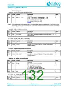
Table 236: WATCHDOG_REG (0x50003100)
Bit
Mode Symbol
Description
Reset
15:9
R0/W
WDOG_WEN
0000.000 = Write enable for Watchdog timer
else Write disable. This filter prevents unintentional preset-
ting the watchdog with a SW run-away.
0x0
8
R/W
R/W
WDOG_VAL_NEG
WDOG_VAL
0 = Watchdog timer value is positive.
1 = Watchdog timer value is negative.
0x0
7:0
Write: Watchdog timer reload value. Note that all bits 15-9
must be 0 to reload this register.
0xFF
Read: Actual Watchdog timer value. Decremented by 1
every 10.24 msec. Bit 8 indicates a negative counter value.
2, 1, 0, 1FF , 1FE etc. An NMI or WDOG (SYS) reset is
16
16
generated under the following conditions:
If WATCHDOG_CTRL_REG[NMI_RST] = 0 then
If WDOG_VAL = 0 -> NMI (Non Maskable Interrupt)
if WDOG_VAL = 1F0 -> WDOG reset -> reload FF
16
16
If WATCHDOG_CTRL_REG[NMI_RST] = 1 then
if WDOG_VAL <= 0 -> WDOG reset -> reload FF
16
Datasheet
Revision 3.4
09-Nov-2016
CFR0011-120-01
134 of 155
© 2014 Dialog Semiconductor

 DIALOG [ Dialog Semiconductor ]