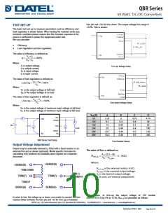
soldering profiles are shown in the next two figures
Operating Temperature Range
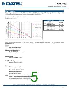
The QBR series converters can be operated over a wide case
temperature range of -40°C to + 105°C. Consideration must be given
to the derating curves when maximum power is drawn from the
converter. The maximum power drawn from open half brick models is
influenced by multiple factors, such as:
Lead Free Wave Soldering Profile
300
250
200
150
100
50
•
•
•
Input voltage range
Output load current
Forced air or natural convection
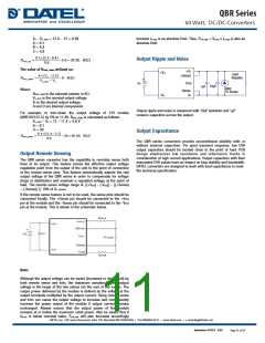
Output Voltage Adjustment
0
The next page describes in detail how to trim the output voltage with
respect to its set point. The output voltage on all models is adjustable
within the range of +10% to –10%.
0
50
100
150
Time (Seconds)
Note:
1. Soldering Materials: Sn/Cu/Ni
2. Ramp up rate during preheat: 1.4 ℃/Sec (From+ 50℃ to +100℃)
3. Soaking temperature: 0.5 ℃/Sec (From +100℃ to+ 130℃), 60
20 seconds
4. Peak temperature: +260℃, above+ 250℃ 3~6 Seconds
5. Ramp up rate during cooling: -10.0 ℃/Sec (From+ 260℃ to
+150℃)
Over Current Protection
All models have internal over current and continuous short circuit
protection. Once the fault condition is removed, the unit will operate
normally. The converter will go into hiccup mode protection once the
point of current limit inception is reached.
Output Overvoltage Protection
The output overvoltage protection consists of circuitry that internally
limits the output voltage. If more accurate output over voltage
protection is required then an external circuit can be used via the
Remote On/Off pin.
Remote On/Off
The QBR series allows the user to switch the module on and off
electronically with the remote on/off feature. All models are available
in “positive logic” and “negative logic” (optional) versions. The
converter turns on if the remote on/off pin is high (>3.5Vdc or open
circuit). Setting the pin low (<1.2Vdc) will turn the Converter off. The
signal level of the remote on/off input is defined with respect to
ground. If not using the remote on/off pin, leave the pin open
(converter will be on). Models with part number suffix “N” are the
“negative logic” remote on/off version. The unit turns off if the remote
on/off pin is high (>3.5Vdc or open circuit). The converter turns on if
the on/off pin input is low (<1.2Vdc). Note that the converter is off by
default.
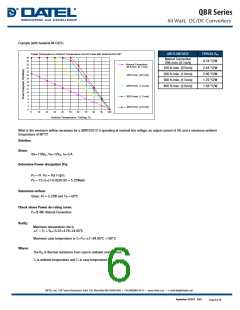
Convection Requirements for Cooling
To predict the approximate cooling needed for the Quarter brick
module, refer to the power derating curves. These derating curves are
approximations of the ambient temperatures and airflows required to
keep the power module temperature below its maximum rating. Once
the module is assembled in the actual system, the module’s
temperature should be monitored to ensure it does not exceed +100°C
as measured at the center of the top of the case (thus verifying proper
cooling).
UVLO (Under voltage Lock Out)
Input under voltage lockout is standard on the QBR unit. The unit will
shut down when the input voltage drops below a threshold, and the
unit will operate when the input voltage goes above the upper
threshold.
Thermal Considerations
Over Temperature Protection
The power module operates in a variety of thermal environments;
however, sufficient cooling should be provided to help ensure reliable
operation of the unit. Heat is removed by conduction, convection, and
radiation to the surrounding environment. The power output of the
module should not be allowed to exceed rated power (Vo_set x Io_max).
The power modules have through-threaded, M3 x0.5 mounting holes,
which enable heat sinks or cold plates to be attached to the module.
Thermal de-rating with heat sinks is expressed by using the overall
thermal resistance of the module (Rca).
These modules have an over temperature protection circuit to
safeguard against thermal damage. Shutdown occurs with the
maximum case reference temperature is exceeded. The module will
restart when the case temperature falls below over temperature
shutdown threshold.
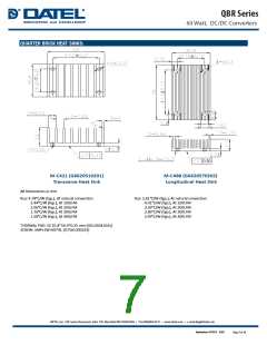
PCB Foot print, Recommended Layout, and
Soldering Information
The end user of the converter must ensure that other components and
metal in the vicinity of the converter meet the spacing requirements to
which the system is approved. Low resistance and low inductance PCB
layout traces should be used where possible. Careful consideration
must also be given to proper low impedance tracks between power
module, input and output grounds. The recommended footprints and
September 18 2017 B.03
Page 9 of 15

 DATEL [ DATEL, Inc. ]