Vo – Vo_nom = 12.6 – 12 = 0.6V
because Io.max is an absolute limit. Thus, Pout.max = Vo.set x Io.max is also an
absolute limit.
A = 9.1
B = 0.4
C = 5.8
9.1×
(
2.5 -0.4
)
− 5.8 = 26.05
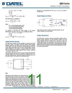
Output Ripple and Noise
Rtrim_up
=
(
KΩ
)
0.6
The value of Rtrim_down defined as:
+Vo
+Sense
+Vin
Load
Resistor
A×
(
Vo − 2.5
)
−D
Rtrim_down
=
(
KΩ
)
+
Vo_nom − Vo
Vin
Trim
10µF
1µF
-
BNC
To Scope
Where:
-Sense
-Vo
Rtrim_down is the external resistor in KΩ.
o_nom is the nominal output voltage.
-Vin
V
Vo is the desired output voltage.
A and D are internal components.
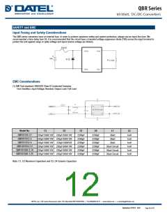
Output ripple and noise is measured with 10µF tantalum and 1µF
ceramic capacitors across the output.
For example: to trim-down the output voltage of 12V module
(QBR101S12-5) by 5% to 11.4V, Rtrim_down is calculated as follows:
V
o_nom – Vo = 12 – 11.4 = 0.6 V
A = 9.1
D = 39
Output Capacitance
9.1×
(
11.4 − 2.5
0.6
)
− 39 = 95.98
Rtrim_down
=
(
KΩ
)
The QBR series converters provide unconditional stability with or
without external capacitors. For good transient response, low ESR
output capacitors should be located close to the point of load. PCB
design emphasizes low resistance and inductance tracks in
consideration of high current applications. Output capacitors with their
associated ESR values have an impact on loop stability and bandwidth.
DATEL converters are designed to work with load capacitance to meet
the technical specification.
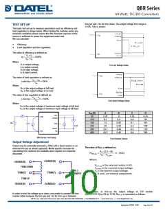
Output Remote Sensing
The QBR series converter has the capability to remotely sense both
lines of its output. This feature moves the effective output voltage
regulation point from the output of the unit to the point of connection
of the remote sense pins. This feature automatically adjusts the real
output voltage of the QBR series in order to compensate for voltage
drops in distribution and maintain a regulated voltage at the point of
load. The remote-sense voltage range is: [(+Vout) - (-Vout)] – [(+Sense)
– (-Sense)] ≦ 10% of Vo_nominal
If the remote sense feature is not to be used, the sense pins should be
connected locally. The +Sense pin should be connected to the +Vout
pin at the module and the -Sense pin should be connected to the -Vout
pin at the module. This is shown in the schematic below.
Note:
Although the output voltage can be varied (increased or decreased) by
both remote sense and trim, the maximum variation for the output
voltage is the larger of the two values not the sum of the values. The
output power delivered by the module is defined as the voltage at the
output terminals multiplied by the output current. Using remote sense
and trim can cause the output voltage to increase and consequently
increase the power output of the module if output current remains
unchanged. Always ensure that the output power of the module
remains at or below the maximum rated power. Also be aware that if
Vo.set is below nominal value, Pout.max will also decrease accordingly
September 18 2017 B.03
Page 11 of 15

 DATEL [ DATEL, Inc. ]