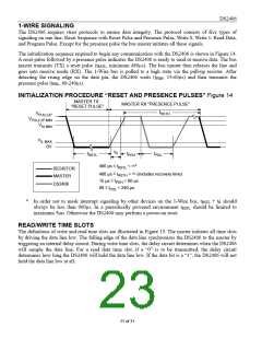
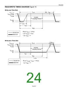
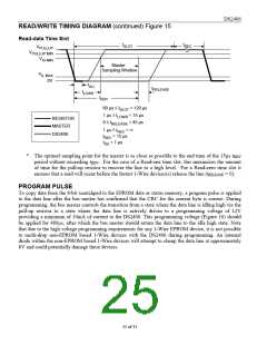
DS2406
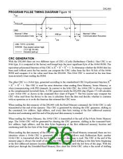
the command byte into the cleared CRC generator, followed by the two address bytes and the Redirection
Byte. Subsequent passes through the Extended Read Memory flow chart will generate a 16-bit CRC that
is the result of clearing the CRC generator and then shifting in only the Redirection Byte.
When writing to the DS2406 (either data memory or status memory), the bus master receives a 16-bit
CRC to verify that the data transfer was correct before applying the programming pulse. With the initial
pass through the Write Memory/Status flow chart the 16-bit CRC will be generated by clearing the CRC-
generator, shifting in the command, low address, high address and the data byte. Subsequent passes
through the Write Memory/Status flow chart due to the DS2406 automatically incrementing its address
counter will generate a 16-bit CRC that is the result of loading (not shifting) the new (incremented)
address into the CRC generator and then shifting in the new data byte.
When communicating with a PIO channel using the Channel Access command, one can select whether
and how often a 16-bit CRC will be added to the data stream. This CRC selection is specified in the
Channel Control byte 1 and may be changed with every execution of the Channel Access command.
Depending on the CRC selection, the device can generate a CRC after every byte that follows the
Channel Info byte, after each block of eight bytes or after each block of 32 bytes. If the CRC is enabled,
with the initial pass through the Channel Access flow chart the 16-bit CRC will be generated by clearing
the CRC-generator, shifting in the command, Channel Control Bytes 1 and 2, Channel Info Byte and the
specified amount of data bytes (1, 8, or 32). Subsequent passes through the Channel Access flow chart
will generate a 16-bit CRC that is the result of clearing the CRC generator and then shifting in the new
data byte(s). This algorithm is valid for all accesses to the PIO channels, continuous reading or writing as
well as toggling between read and write.
The comparison of CRC values and decision to continue with an operation are determined entirely by the
bus master. There is no circuitry on the DS2406 that prevents a command sequence from proceeding if a
CRC error occurs. For more details on generating CRC values including example implementations in
both hardware and software, see Application Note 27.
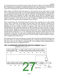
CRC-16 HARDWARE DESCRIPTION AND POLYNOMIAL Figure 17
16
15
2
Polynomial = X + X + X + 1
1ST
2ND
3RD
4TH
5TH
6TH
7TH
8TH
STAGE
STAGE
STAGE STAGE STAGE STAGE STAGE STAGE
0
1
2
3
4
5
6
7
8
X
X
X
X
X
X
X
X
X
R
S
16TH
STAGE
9TH
10TH
11TH
12TH
13TH
14TH
15TH
STAGE STAGE STAGE STAGE STAGE STAGE STAGE
9
10 11 12 13 14
15
16
X
X
X
X
X
X
X
X
CRC
OUTPUT
INPUT DATA
27 of 31

 DALLAS [ DALLAS SEMICONDUCTOR ]