DS2406
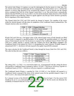
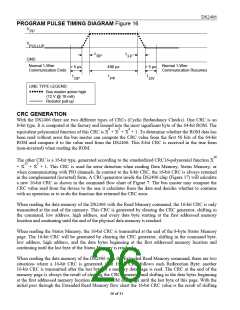
PROGRAM PULSE TIMING DIAGRAM Figure 16
V
PP
V
PULLUP
t
t
RP
FP
GND
Normal 1-Wire
Communication Ends
Normal 1-Wire
Communication Resumes
> 5 µs
480 µs
> 5 µs
t
t
t
DP
PP
DV
LINE TYPE LEGEND:
Bus master active high
(12 V @ 10 mA)
Resistor pull-up
CRC GENERATION
With the DS2406 there are two different types of CRCs (Cyclic Redundancy Checks). One CRC is an
8-bit type. It is computed at the factory and lasered into the most significant byte of the 64-bit ROM. The
equivalent polynomial function of this CRC is X8 + X5 + X4 + 1. To determine whether the ROM data has
been read without error the bus master can compute the CRC value from the first 56 bits of the 64-bit
ROM and compare it to the value read from the DS2406. This 8-bit CRC is received in the true form
(non-inverted) when reading the ROM.
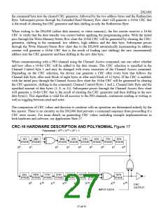
The other CRC is a 16-bit type, generated according to the standardized CRC16-polynomial function X16
+ X15 + X2 + 1. This CRC is used for error detection when reading Data Memory, Status Memory, or
when communicating with PIO channels. In contrast to the 8-bit CRC, the 16-bit CRC is always returned
in the complemented (inverted) form. A CRC-generator inside the DS2406 chip (Figure 17) will calculate
a new 16-bit CRC as shown in the command flow chart of Figure 7. The bus master may compare the
CRC value read from the device to the one it calculates from the data and decides whether to continue
with an operation or to re-do the function that returned the CRC error.
When reading the data memory of the DS2406 with the Read Memory command, the 16-bit CRC is only
transmitted at the end of the memory. This CRC is generated by clearing the CRC generator, shifting in
the command, low address, high address, and every data byte starting at the first addressed memory
location and continuing until the end of the physical data memory is reached.
When reading the Status Memory, the 16-bit CRC is transmitted at the end of the 8-byte Status Memory
page. The 16-bit CRC will be generated by clearing the CRC generator, shifting in the command byte,
low address, high address, and the data bytes beginning at the first addressed memory location and
continuing until the last byte of the Status Memory is reached.
When reading the data memory of the DS2406 with the Extended Read Memory command, there are two
situations where a 16-bit CRC is generated. One 16-bit CRC follows each Redirection Byte; another
16-bit CRC is transmitted after the last byte of a memory data page is read. The CRC at the end of the
memory page is always the result of clearing the CRC generator and shifting in the data bytes beginning
at the first addressed memory location of the EPROM data page until the last byte of this page. With the
initial pass through the Extended Read Memory flow chart the 16-bit CRC value is the result of shifting
26 of 31

 DALLAS [ DALLAS SEMICONDUCTOR ]