DS1921H/Z
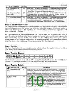
BIT DESCRIPTION
BIT(S)
DEFINITION
TLS: Temperature Low
Alarm Search
b2
If this bit is 1, the device will respond to a Conditional Search command
if during a mission the temperature has reached or is lower than the Low
Temperature Threshold stored at address 020Bh.
THS: Temperature High
Alarm Search
b1
b0
If this bit is 1, the device will respond to a Conditional Search command
if during a mission the temperature has reached or is higher than the
High Temperature Threshold stored at address 020Ch.
TAS: Timer Alarm Search
If this bit is 1, the device will respond to a Conditional Search command
if during a mission a timer alarm has occurred. Since a timer alarm
cannot be disabled, the TAF flag usually reads 1 during a mission.
Therefore it may be advisable to set the TAS bit to a 0, in most cases.
Mission Start Delay Counter
The content of the Mission Start Delay Counter determines how many minutes the device will wait before
starting the logging process. The mission start delay value is stored as unsigned 16-bit integer number at
addresses 212h (low byte) and 213h (high byte). The maximum delay is 65535 minutes, equivalent to 45
days, 12 hours, and 15 minutes.
For a typical mission, the Mission Start Delay is 0. If a mission is too long for a single DS1921H/Z to
store all temperature readings at the selected sample rate, one can use several devices, staggering the
Mission Start Delay to record the full period. In this case, the RO bit in the control register (address
020Eh) must be set to 0 to prevent overwriting of the recorded temperature log after the datalog memory
is full. See Mission Start and Logging Process description and flow chart for details.
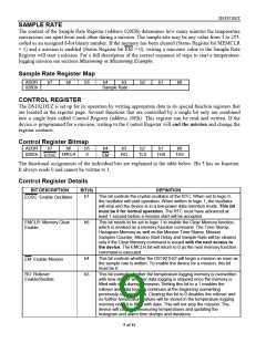
Status Register
The Status Register holds device status information and alarm flags. The register is located at address
214h. Writing to this register will not necessarily end a mission.
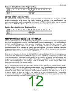
Status Register Bitmap
ADDR
0214h
b7
b6
MEMCLR
b5
b4
b3
0
b2
b1
b0
MIP
SIP
TLF
THF
TAF
TCB
The functional assignments of the individual bits are explained in the table below. The bits MIP, TLF,
THF and TAF can only be written to 0. All other bits are read-only. Bit 3 has no function.
Status Register Details
BIT DESCRIPTION
BIT(S)
DEFINITION
b7
If this bit reads 0 the DS1921H/Z is currently performing a temperature
conversion, either self-initiated because of a mission being in progress
or initiated by a command when a mission is not in progress. The TCB
bit goes low just before a conversion starts and returns to high just after
the result is latched into the readout register at address 0211h.
TCB: Temperature Core
Busy
MEMCLR: Memory
Cleared
b6
If this bit reads 1, the memory pages 17 and higher (alarm time
stamps/durations, temperature histogram, excluding datalog memory),
as well as the Mission Time Stamp, Mission Samples Counter, Mission
Start Delay and Sample Rate have been cleared to 0 from executing a
Clear Memory function command. The MEMCLR bit will return to 0 as
soon as writing a non-0 value to the Sample Rate Register starts a new
mission, provided that the EM bit is also 0. The memory has to be
cleared in order for a mission to start.
10 of 44

 DALLAS [ DALLAS SEMICONDUCTOR ]