DS1921H/Z
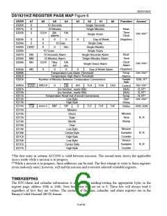
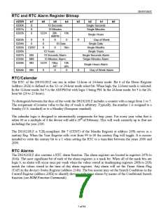
DS1921H/Z REGISTER PAGE MAP Figure 6
ADDR
0200h
0201h
0202h
b7
0
b6
b5
b4
b3
b2
b1
b0
Function
Access*
10 Seconds
10 Minutes
Single Seconds
Single Minutes
0
Real-
Time
Clock
0
12/24
20h.
AM/PM
10h.
0
R/W; R/W**
Single Hours
0203h
0204h
0
0
0
0
0
0
0
Day of Week
Registers
10 Date
Single Date
Single Months
0205h CENT
0206h
0
10m.
10 Years
Single Years
Real-
Time
0207h
0208h
0209h
MS
MM
MH
10 Seconds Alarm
10 Minutes Alarm
Single Seconds Alarm
Single Minutes Alarm
Clock
Alarm
12/24
10ha.
A/P
10h.
R/W; R/W**
R/W; R/W**
Single Hours Alarm
alm.
Registers
Temp.
Alarms
Sample
Rate
020Ah
020Bh
020Ch
020Dh
MD
0
0
0
0
Day of Week Alarm
Temperature Low Alarm Threshold
Temperature High Alarm Threshold
Number of Minutes Between Temperature Conversions
R/W; R**
EMCLR
R/W; R/W**
020Eh
0
RO
TLS
THS
TAS
TAF
Control
(N/A)
(N/A)
Temp.
Start
Delay
EOSC
EM
020Fh
0210h
0211h
0212h
0213h
0214h
(no function, reads 00h)
(no function, reads 00h)
R; R**
R; R**
R; R**
Temperature Read Out (Forced Conversion)
Low Byte
High Byte
R/W; R/W**
MEMCLR
MIP
SIP
Minutes
0
TLF
THF
Status
R/W; R/W
R; R
TCB
0215h
0216h
0217h
0218h
0219h
021Ah
021Bh
021Ch
021Dh
021Eh
021Fh
Mission
Time
Hours
Date
Stamp
Month
Year
Mission
Samples
Counter
Device
Low Byte
Center Byte
High Byte
Low Byte
R; R
R; R
Samples
Counter
Center Byte
High Byte
*The first entry in column ACCESS is valid between missions. The second entry shows the applicable
access mode while a mission is in progress.
**While a mission is in progress, these addresses can be read. The first attempt to write to these registers
(even read-only ones), however, will end the mission and overwrite selected writeable registers.
TIMEKEEPING
The RTC/alarm and calendar information is accessed by reading/writing the appropriate bytes in the
register page, address 200h to 206h. Note that some bits are set to 0. These bits will always read 0
regardless of how they are written. The contents of the time, calendar, and alarm registers are in the
Binary-Coded Decimal (BCD) format.
6 of 44

 DALLAS [ DALLAS SEMICONDUCTOR ]