ES51963
4 1/2 DMM
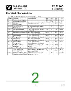
Electrical Characteristics
TA=25°C, DGND=AGND=0V, operating clock = 4 MHz.
Symbol Parameter
Test Condition
Min. Typ. Max.
Unit
V
V+
V-
Positive Power Supply
Negative Power Supply
2.3
-2.3
-
2.5
-2.5
1.0
3.3
-3.3
1.7
V
I(V+) Operation
Normal power on (V+ to V-)
mA
Supply Current
I(GND) Supply Current of
DGND to V-
Zero
5
10
0
-
-
mA
count
%F.S.
%F.S.
%F.S.
%F.S.
V
∆V between DGND and V-
is -0.2V
1 MΩ input resistor, null to
zero by uP.
Zero Input Reading
-0
+0
NLV1 Nonlinearity (Voltage x1) Best case straight line
conversion rate = 10 times/s
-0.02
-0.02
-0.04
-0.04
0.02
0.02
0.04
0.04
REV1 Rollover Error
(Voltage x1)
-
1 MΩ input resistor
conversion rate = 10 times/s
Best case straight line
conversion rate = 10 times/s
1 MΩ input resistor
NLV10 Nonlinearity
(Voltage x10)
-
REV10 Rollover Error
(Voltage x10)
-
conversion rate = 10 times/s
100 kΩ between V12 and
AGND
V12
Band Gap Voltage
Reference
-1.31 -1.23 -1.10
LBATT Low Battery Detection LBATT to V12
-60
-1.2
-25
0
-
60
mV
PEAK Hold value
+1.2 %F.S.
使用 10nF 聚㆚酯薄膜電容
(polyester, Mylar)
accuracy (10us)
TCRF Reference Voltage (V12)
Temperature Coefficient
+25
-
±count
ppm/°C
-
50
100 kΩ between V12 and
AGND (0°C to 70°C)
2
2003/9/1

 CYRUSTEK [ Cyrustek corporation ]