SL811HS
TABLE OF CONTENTS
1.0 CONVENTIONS ..............................................................................................................................4
2.0 DEFINITIONS ..................................................................................................................................4
3.0 REFERENCES ................................................................................................................................4
4.0 INTRODUCTION .............................................................................................................................4
4.1 Block Diagram ................................................................................................................................4
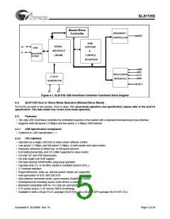
4.2 SL811HS Host or Slave Mode Selection [Master/Slave Mode] ..................................................5
4.3 Features ..........................................................................................................................................5
4.4 Data Port, Microprocessor Interface ............................................................................................6
4.5 Interrupt Controller ........................................................................................................................6
4.6 Buffer Memory ...............................................................................................................................6
4.7 PLL Clock Generator .....................................................................................................................6
4.8 USB Transceiver ............................................................................................................................8
5.0 SL811HS REGISTERS ...................................................................................................................8
5.1 Register Values on Power-up and Reset .....................................................................................9
5.2 USB Control Registers ..................................................................................................................9
5.3 SL811HS Control Registers ........................................................................................................12
6.0 SL811HS AND SL811HST-AC PHYSICAL CONNECTIONS ......................................................16
6.1 SL811HS Physical Connections .................................................................................................16
6.2 SL811HST-AC Physical Connections ........................................................................................19
7.0 ELECTRICAL SPECIFICATIONS .................................................................................................22
7.1 Absolute Maximum Ratings ........................................................................................................22
7.2 Recommended Operating Condition ........................................................................................22
7.3 External Clock Input Characteristics (X1) .................................................................................22
7.4 DC Characteristics .......................................................................................................................23
7.5 USB Host Transceiver Characteristics ......................................................................................23
7.6 Bus Interface Timing Requirements ..........................................................................................24
8.0 PACKAGE DIAGRAMS ..............................................................................................................28
LIST OF FIGURES
Figure 4-1. SL811HS USB Host/Slave Controller Functional Block Diagram ................................ 5
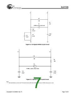
Figure 4-2. Full-Speed 48-MHz Crystal Circuit .................................................................................. 7
Figure 4-3. Optional 12-MHz Crystal Circuit ...................................................................................... 7
Figure 6-1. SL811HS USB Host/Slave Controller—Pin Layout ......................................................16
Figure 6-2. SL811HST-AC USB Host/Slave Controller Pin Layout ................................................ 19
LIST OF TABLES
Table 6-1. SL811HS Pin Assignments and Definitions ...................................................................17
Table 6-2. SL811HST-AC Pin Assignments and Definitions ...........................................................20
Document #: 38-08008 Rev. *A
Page 2 of 29

 CYPRESS [ CYPRESS ]