SL811HS
USB Control Registers
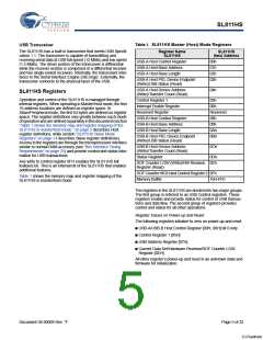
The SL811HS USB Host Control has two groups of five registers
each which map in the SL811HS memory space. These registers
are defined in the following tables.
Communication and data flow on the USB bus uses the
SL811HS’ USB A-B Control registers. The SL811HS communi-
cates with any USB Device function and any specific endpoint
via the USB-A or USB-B register sets.
Table 2. SL811HS Host Control Registers
SL811HS
Register Name SL811H
The USB A-B Host Control registers are used in an overlapped
configuration to manage traffic on the USB bus. The USB Host
Control register also provides a means to interrupt an external
CPU or microcontroller when one of the USB protocol transac-
tions is completed. Table 1 and Table 2 show the two sets of USB
Host Control registers, the ’A’ set and ’B’ set. The two register
sets allow for overlapping operation. When one set of param-
eters is being set up, the other is transferring. On completion of
a transfer to an endpoint, the next operation is controlled by the
other register set.
(hex) Address
USB-A Host Control Register
USB-A Host Base Address
USB-A Host Base Length
00h
01h
02h
03h
USB-A Host PID, Device Endpoint
(Write)/USB Status (Read)
USB-A Host Device Address
(Write)/Transfer Count (Read)
04h
Note The USB-B register set is used only when SL811HS mode
is enabled by initializing register 0FH.
USB-B Host Control Register
USB-B Host Base Address
USB-B Host Base Length
08h
09h
0Ah
0Bh
USB-B Host PID, Device Endpoint
(Write)/USB Status (Read)
USB-B Host Device Address
(Write)/Transfer Count (Read)
0Ch
Document 38-08008 Rev. *F
Page 6 of 32
[+] Feedback

 CYPRESS [ CYPRESS ]