CY8C9520A, CY8C9540A
CY8C9560A
an EEPROM write sequence. If the end of available EEPROM
space is reached, then further writes are responded to with a
NAK.
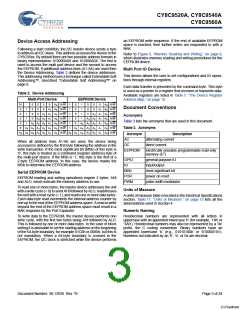
Device Access Addressing
Following a start condition, the I2C master device sends a byte
to address an I2C slave. This address accesses the device in the
CY8C95xx. By default there are two possible address formats in
binary representation: 010000A0X and 101000A0X. The first is
used to access the multi port device and the second to access
the EEPROM. If additional address lines (A1-A6) are used then
the Device Addressing. Table 2 defines the device addresses.
This addressing method uses a technique called Extendable Soft
Addressing™, described “Extendable Soft Addressing™” on
page 8.
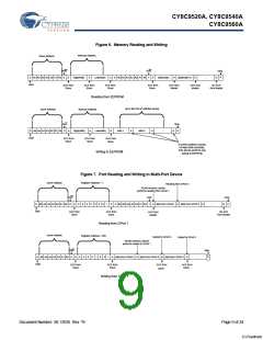
Refer to Figure 6, “Memory Reading and Writing,” on page 9,
which illustrates memory reading and writing procedures for the
EEPROM device.
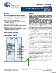
Multi Port IO Device
This device allows the user to set configurations and IO opera-
tions through internal registers.
Each data transfer is preceded by the command byte. This byte
is used as a pointer to a register that receives or transmits data.
Available registers are listed in Table 7, “The Device Register
Address Map,” on page 10.
Table 2. Device Addressing
Multi-Port Device
EEPROM Device
01
0
0
0
0
0
0
0
0
0
0
0
A
A
A
A
A
A
A
R/W
R/W
R/W
R/W
R/W
R/W
R/W
1
1
1
1
1
1
0
0
0
0
0
1
1
1
1
0
0
0
0
0
0
A
A
A
A
A
A
A
R/W
R/W
R/W
R/W
R/W
R/W
R/W
0
0
0
0
0
0
0
0
0
0
0
0
0
0
Document Conventions
1
1
1
1
A
A
1
1
1
1
1
1
1
1
1
1
1
1
0
A
A
A
A
A
A
A
A
A
A
A
A
2
2
2
2
2
2
2
2
2
2
Acronyms
0
A
A
A
A
A
A
A
A
A
A
3
3
3
3
3
3
3
3
Table 3 lists the acronyms that are used in this document.
0
A
A
A
A
A
A
A
A
4
4
4
4
4
4
0
A
A
A
A
A
A
Table 3. Acronyms
5
5
5
5
A
A
A
A
6
6
Acronym
AC
Description
alternating current
When all address lines A1-A6 are used, the device being
accessed is defined by the first byte following the address in the
write transaction. If the most significant bit (MSb) of this byte is
‘0’, this byte is treated as a command (register address) byte of
the multi-port device. If the MSb is ‘1’, this byte is the first of a
2-byte EEPROM address. In this case, the device masks the
MSb to determine the EEPROM address.
DC
direct current
EEPROM
electrically erasable programmable read-only
memory (E2)
GPIO
IO
general purpose IO
input/output
MSb
POR
PWM
most-significant bit
power on reset
Serial EEPROM Device
EEPROM reading and writing operations require 2 bytes, AHI
and ALO, which indicate the memory address to use.
pulse width modulator
To read one or more bytes, the master device addresses the unit
with a write cycle (= 0) to send AHI followed by ALO, readdresses
the unit with a read cycle (= 1), and reads one or more data bytes.
Each data byte read increments the internal address counter by
one up to the end of the EEPROM address space. A read or write
beyond the end of the EEPROM address space must result in a
NAK response by the Port Expander.
Units of Measure
A units of measure table is located in the Electrical Specifications
section. Table 17, “Units of Measure,” on page 15 lists all the
abbreviations used in Section 4.
Numeric Naming
To write data to the EEPROM, the master device performs one
write cycle, with the first two bytes being AHI followed by ALO.
This is followed by one or more data bytes. In the case of block
writing it is advisable to set the starting address on the beginning
of the 64-byte boundary, for example 01C0h or 0080h, but this is
not mandatory. When a 64-byte boundary is crossed in the
EEPROM, the I2C clock is stretched while the device performs
Hexidecimal numbers are represented with all letters in
uppercase with an appended lowercase ‘h’ (for example, ‘14h’ or
‘3Ah’). Hexidecimal numbers may also be represented by a ‘0x’
prefix, the C coding convention. Binary numbers have an
appended lowercase ‘b’ (e.g., 01010100b’ or ‘01000011b’).
Numbers not indicated by an ‘h’, ‘b’, or 0x are decimal.
Document Number: 38-12036 Rev. *B
Page 3 of 24
[+] Feedback

 CYPRESS [ CYPRESS ]