PSoC® 3: CY8C32 Family
Data Sheet
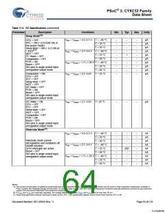
11.3.3 Inductive Boost Regulator.
Table 11-6. Inductive Boost Regulator DC Specifications
Unless otherwise specified, operating conditions are: VBAT = 2.4 V, VOUT = 2.7 V, IOUT = 40 mA, FSW = 400 kHz, LBOOST = 10 µH,
BOOST = 22 µF || 0.1 µF
C
Parameter Description
VBAT
Conditions
T=-35 °C to +65 °C
Min
0.5
0.68
–
Typ
–
Max
3.6
3.6
50
Units
V
Input voltage
Includes startup
Over entire temperature range
–
V
IOUT
Load current[23, 24]
VBAT = 1.6 – 3.6 V, VOUT = 3.6 – 5.0 V,
external diode
–
mA
VBAT = 1.6 – 3.6 V, VOUT = 1.6 – 3.6 V,
internal diode
–
–
–
–
–
–
–
–
75
30
20
15
mA
mA
mA
mA
VBAT = 0.8 – 1.6 V, VOUT = 1.6 – 3.6 V,
internal diode
VBAT = 0.8 – 1.6 V, VOUT = 3.6 – 5.0 V,
external diode
VBAT = 0.5 – 0.8 V, VOUT = 1.6 – 3.6 V,
internal diode
ILPK
IQ
Inductor peak current
Quiescent current
–
–
–
–
700
–
mA
µA
µA
Boost active mode
200
12
Boost standby mode, 32 khz external crystal
oscillator, IOUT < 1 ìA
–
VOUT
Boost voltage range[25, 26]
1.8 V
1.71
1.81
1.90
2.28
2.57
2.85
3.14
3.42
4.75
–
1.80
1.90
2.00
2.40
2.70
3.00
3.30
3.60
5.00
–
1.89
2.00
2.10
2.52
2.84
3.15
3.47
3.78
5.25
3.8
V
V
1.9 V
2.0 V
V
2.4 V
V
2.7 V
V
3.0 V
V
3.3 V
V
3.6 V
V
5.0 V
External diode required
V
RegLOAD
RegLINE
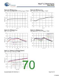
η
Load regulation
Line regulation
Efficiency
%
%
%
%
–
–
4.1
LBOOST = 10 µH
LBOOST = 22 µH
70
85
–
82
90
–
Notes
23. For output voltages above 3.6 V, an external diode is required.
24. Maximum output current applies for output voltages ≤ 4x input voltage.
25. Based on device characterization (Not production tested).
26. At boost frequency of 2 MHz, VOUT is limited to 2 x VBAT. At 400 kHz, VOUT is limited to 4 x VBAT
.
Document Number: 001-56955 Rev. *J
Page 68 of 119
[+] Feedback

 CYPRESS [ CYPRESS ]