PSoC® 3: CY8C32 Family
Data Sheet
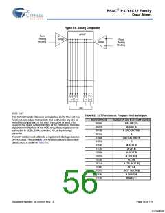
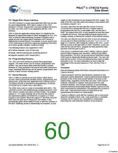
Figure 8-6. Analog Comparator
ANAIF
From
Analog
Routing
+
comp0
_
+
_
From
Analog
Routing
comp1
4
4
4
4
4
4
4
4
LUT0
LUT1
LUT2
LUT3
UDBs
8.3.2 LUT
Table 8-2. LUT Function vs. Program Word and Inputs
The CY8C32 family of devices contains four LUTs. The LUT is a
two input, one output lookup table that is driven by any one or
two of the comparators in the chip. The output of any LUT is
routed to the digital system interface of the UDB array. From the
digital system interface of the UDB array, these signals can be
connected to UDBs, DMA controller, I/O, or the interrupt
controller.
Control Word
0000b
0001b
0010b
0011b
0100b
0101b
0110b
0111b
Output (A and B are LUT inputs)
FALSE (‘0’)
A AND B
A AND (NOT B)
A
The LUT control word written to a register sets the logic function
on the output. The available LUT functions and the associated
control word is shown in Table 8-2.
(NOT A) AND B
B
A XOR B
A OR B
1000b
1001b
1010b
1011b
1100b
1101b
1110b
A NOR B
A XNOR B
NOT B
A OR (NOT B)
NOT A
(NOT A) OR B
A NAND B
TRUE (‘1’)
1111b
Document Number: 001-56955 Rev. *J
Page 56 of 119
[+] Feedback

 CYPRESS [ CYPRESS ]