CY8C21x34 Final Data Sheet
PSoC® Overview
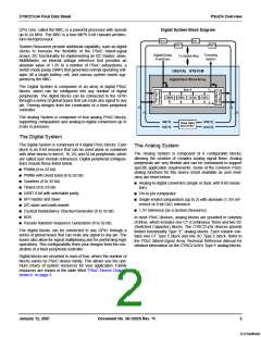
Analog System Block Diagram
Additional System Resources
System Resources, some of which have been previously listed,
provide additional capability useful to complete systems. Addi-
tional resources include a switch mode pump, low voltage
detection, and power on reset. Brief statements describing the
merits of each system resource are presented below.
Array Input
Configuration
■ Digital clock dividers provide three customizable clock fre-
quencies for use in applications. The clocks can be routed to
both the digital and analog systems. Additional clocks can be
generated using digital PSoC blocks as clock dividers.
ACI0[1:0]
ACI1[1:0]
■ The I2C module provides 100 and 400 kHz communication
over two wires. Slave, master, and multi-master modes are
all supported.
All IO
X
X
■ Low Voltage Detection (LVD) interrupts can signal the appli-
cation of falling voltage levels, while the advanced POR
(Power On Reset) circuit eliminates the need for a system
supervisor.
AC OL 1MU X
X
X
An al o g MuxBus
X
Array
■ An internal 1.3 voltage reference provides an absolute refer-
ACE00
ACE01
ASE11
ence for the analog system, including ADCs and DACs.
■ An integrated switch mode pump (SMP) generates normal
operating voltages from a single 1.2V battery cell, providing a
low cost boost converter.
ASE10
■ Versatile analog multiplexer system.
PSoC Device Characteristics
The Analog Multiplexer System
Depending on your PSoC device characteristics, the digital and
analog systems can have 16, 8, or 4 digital blocks and 12, 6, or
4 analog blocks. The following table lists the resources
available for specific PSoC device groups. The PSoC device
covered by this data sheet is highlighted below.
The Analog Mux Bus can connect to every GPIO pin. Pins can
be connected to the bus individually or in any combination. The
bus also connects to the analog system for analysis with com-
parators and analog-to-digital converters. An additional 8:1 ana-
log input multiplexer provides a second path to bring Port 0 pins
to the analog array.
PSoC Device Characteristics
Switch control logic enables selected pins to precharge continu-
ously under hardware control. This enables capacitive mea-
surement for applications such as touch sensing. Other
multiplexer applications include:
PSoC Part
Number
up to
64
CY8C29x66
4
16
12
4
4
12
2K
32K
■ Track pad, finger sensing.
up to
44
256
Bytes
CY8C27x43
CY8C24x94
CY8C24x23A
2
1
1
8
4
4
12
48
12
4
2
2
4
2
2
12
6
16K
16K
4K
■ Chip-wide mux that allows analog input from any IO pin.
■ Crosspoint connection between any IO pin combinations.
56
1K
up to
24
256
Bytes
6
When designing capacitive sensing applications, refer to the
signal-to-noise system level requirement found in Application
Note AN2403 at http://www.cypress.com/design/AN2403 on the
Cypress web site.
up to
28
512
Bytes
a
CY8C21x34
CY8C21x23
CY8C20x34
1
1
0
4
4
0
28
8
0
0
0
2
2
0
8K
4K
8K
4
256
Bytes
a
16
4
up to
28
512
Bytes
b
28
3
a. Limited analog functionality.
b. Two analog blocks and one CapSense.
January 12, 2007
Document No. 38-12025 Rev. *K
3
[+] Feedback

 CYPRESS [ CYPRESS ]