CY8C21x34 Final Data Sheet
PSoC® Overview
CPU core, called the M8C, is a powerful processor with speeds
up to 24 MHz. The M8C is a four MIPS 8-bit Harvard architec-
ture microprocessor.
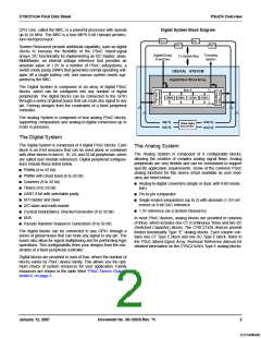
Digital System Block Diagram
Port 3
Port 1
Port 2
Port 0
System Resources provide additional capability, such as digital
clocks to increase the flexibility of the PSoC mixed-signal
arrays, I2C functionality for implementing an I2C master, slave,
MultiMaster, an internal voltage reference that provides an
absolute value of 1.3V to a number of PSoC subsystems, a
switch mode pump (SMP) that generates normal operating volt-
ages off a single battery cell, and various system resets sup-
ported by the M8C.
DigitalClocks
FromCore
ToAnalog
System
To SystemBus
DIGITAL SYSTEM
DigitalPSoCBlockArray
Row 0
The Digital System is composed of an array of digital PSoC
blocks, which can be configured into any number of digital
peripherals. The digital blocks can be connected to the GPIO
through a series of global buses that can route any signal to any
pin. Freeing designs from the constraints of a fixed peripheral
controller.
4
4
DBB00
DBB01
DCB02
DCB03
8
8
8
8
The Analog System is composed of four analog PSoC blocks,
supporting comparators and analog-to-digital conversion up to
8 bits in precision.
GIE[7:0]
GIO[7:0]
GOE[7:0]
GOO[7:0]
Global Digital
Interconnect
The Digital System
The Digital System is composed of 4 digital PSoC blocks. Each
block is an 8-bit resource that can be used alone or combined
with other blocks to form 8, 16, 24, and 32-bit peripherals, which
are called user module references. Digital peripheral configura-
tions include those listed below.
The Analog System
The Analog System is composed of 4 configurable blocks,
allowing the creation of complex analog signal flows. Analog
peripherals are very flexible and can be customized to support
specific application requirements. Some of the common PSoC
analog functions for this device (most available as user mod-
ules) are listed below.
■ PWMs (8 to 32 bit)
■ PWMs with Dead band (8 to 32 bit)
■ Counters (8 to 32 bit)
■ Analog-to-digital converters (single or dual, with 8-bit resolu-
■ Timers (8 to 32 bit)
tion)
■ UART 8 bit with selectable parity
■ SPI master and slave
■ Pin-to-pin comparator
■ Single-ended comparators (up to 2) with absolute (1.3V) ref-
erence or 8-bit DAC reference
■ I2C slave and multi-master
■ Cyclical Redundancy Checker/Generator (8 to 32 bit)
■ IrDA
■ 1.3V reference (as a System Resource)
In most PSoC devices, analog blocks are provided in columns
of three, which includes one CT (Continuous Time) and two SC
(Switched Capacitor) blocks. The CY8C21x34 devices provide
limited functionality Type “E” analog blocks. Each column con-
tains one CT Type E block and one SC Type E block. Refer to
the PSoC Mixed-Signal Array Technical Reference Manual for
detailed information on the CY8C21x34’s Type E analog blocks.
■ Pseudo Random Sequence Generators (8 to 32 bit)
The digital blocks can be connected to any GPIO through a
series of global buses that can route any signal to any pin. The
buses also allow for signal multiplexing and for performing logic
operations. This configurability frees your designs from the con-
straints of a fixed peripheral controller.
Digital blocks are provided in rows of four, where the number of
blocks varies by PSoC device family. This allows you the opti-
mum choice of system resources for your application. Family
resources are shown in the table titled “PSoC Device Charac-
teristics” on page 3.
January 12, 2007
Document No. 38-12025 Rev. *K
2
[+] Feedback

 CYPRESS [ CYPRESS ]