CY7C68300B/CY7C68301B
CY7C68320/CY7C68321
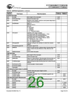
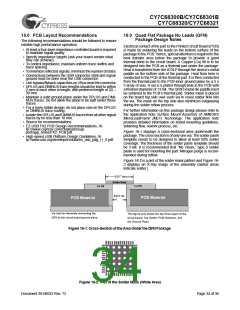
Table 8-7. EEPROM-related Vendor-specific Commands
Label
bmRequestType bRequest
wValue
wIndex
wLength
Data
LOAD_CONFIG_DATA
0x40
0x01
0x0000
30x02 – 0x0F
Data Length
Configuration
Data
READ_CONFIG_DATA
0xC0
0x02
Data Source
Starting Address Data Length
Configuration
Data
address specified by the wIndex field. The wLength field
denotes the length in bytes of data requested from the data
source.
8.6
Programming the EEPROM
There are three methods to program the EEPROM:
• External device programmer
• USB commands listed in Table 8-7
• In-system programming on a bed-of-nails tester.
Any vendor-specific USB write request to the Serial ROM
device configuration space will simultaneously update internal
configuration register values as well. If the I2C device is
programmed without vendor specific USB commands, AT2LP
must be synchronously reset (RESET#) before configuration
data is reloaded.
Legal values for wValue are as follows:
• 0x0000 Configuration bytes, addresses 0x0 – 0xF only
• 0x0002 External I2C memory device
Illegal values for wValue will result in undefined operation.
Attempted reads from an I2C memory device when none is
connected will result in undefined operation. Attempts to read
configuration bytes with starting addresses greater than 0xF
will also result in undefined operation.
The AT2LP supports a subset of the “slow mode” specification
(100 KHz) required for 24LCXXB EEPROM family device
support. Features such as “Multi-Master,” “Clock Synchroni-
zation” (the SCL pin is output only), “10-bit addressing,” and
“CBUS device support” are not supported. Vendor-specific
USB commands allow the AT2LP to address up to 256 bytes
of data.
9.0
Absolute Maximum Ratings
Storage Temperature.................................. –65°C to +150°C
Ambient Temperature with Power Supplied ..... 0°C to +70°C
Supply Voltage to Ground Potential .............–0.5 V to +4.0 V
DC Input Voltage to Any Input Pin............................... 5.25 V
8.6.1
LOAD_CONFIG_DATA
DC Voltage Applied to Outputs
in Hi-Z State......................................... –0.5 V to VCC + 0.5 V
This request enables configuration data writes to the AT2LP’s
configuration space. The wIndex field specifies the starting
address and the wLength field denotes the data length in
bytes.
Power Dissipation..................................................... 300 mW
Static Discharge Voltage.......................................... > 2000 V
Max Output Current Per I/O Port
(D0-D7, D8-15, ATA control)........................................ 10 mA
Legal values for wValue are as follows:
• 0x0000 Configuration bytes, address range 0x2 – 0xF
• 0x0002 External I2C memory device
10.0
Operating Conditions
Configuration-byte writes must be constrained to addresses
0x2 through 0xF, as shown in Table 8-7. Attempts to write
outside this address space will result in undefined operation.
Configuration-byte writes only overwrite AT2LP Configuration
Byte registers, the original data source (I2C memory device)
remains unchanged.
TA (Ambient Temperature Under Bias)............. 0°C to +70°C
Supply Voltage ...........................................+3.15V to +3.45V
Ground Voltage ................................................................. 0V
Fosc (Oscillator or Crystal Frequency).... 24 MHz ± 100 ppm,
.................................................................. Parallel Resonant
8.6.2
READ_CONFIG_DATA
This USB request allows data retrieval from the data source
specified by the wValue field. Data is retrieved beginning at the
Document 38-08033 Rev. *D
Page 30 of 36

 CYPRESS [ CYPRESS ]