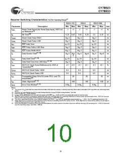
CY7B923
CY7B933
[1]
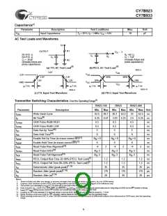
Receiver Switching Characteristics Over the Operating Range
7B933-155
Min. Max
7B933
7B933-400
Parameter
Description
Min.
Max.
Min.
Max. Unit
t
Read Clock Period (No Serial Data Input), REFCLK
as Reference
−1
+1
−1
+1
−1
+1
%
CKR
[15]
[16]
t
t
t
t
t
t
t
Bit Time
6.25 6.67
5t −3
3.03
6.25
2.5
6.25
ns
ns
ns
ns
ns
ns
ns
B
Read Clock Pulse HIGH
Read Clock Pulse LOW
RDY Hold Time
5t −3
5t −3
B
CPRH
CPRL
RH
B
B
5t −3
5t −3
5t −3
B
B
B
t −2.5
t −2.5
t −2.5
B
B
B
RDY Pulse Fall to CKR Rise
RDY Pulse Width HIGH
5t −3
5t −3
5t −3
B
PRF
PRH
A
B
B
4t −3
4t −3
4t −3
B
B
B
[17, 18]
Data Access Time
2t −2 2t + 2t −2
2t +4
2t −2
2t +4
B
B
B
B
B
B
4
[17, 18]
t
t
t
Data Hold Time
t −2.5
t −2.5
t −2.5
ns
ns
%
ROH
B
B
B
[17, 18]
Data Hold Time from CKR Rise
2t −3
2t −3
2t −3
H
B
B
B
REFCLK Clock Period Referenced to CKW of
−0.1 +0.1
−0.1
+0.1
−0.1
+0.1
CKX
[19]
Transmitter
t
t
t
REFCLK Clock Pulse HIGH
6.5
6.5
20
6.5
6.5
6.5
6.5
ns
ns
ns
CPXH
CPXL
DS
REFCLK Clock Pulse LOW
Propagation Delay SI to SO (note PECL and TTL
20
20
[20]
thresholds)
[7, 21]
t
t
Static Alignment
100
100
100
ps
SA
[7, 22]
Error Free Window
0.9t
0.9t
0.9t
B
EFW
B
B
Notes:
15. The period of tCKR will match the period of the transmitter CKW when the receiver is receiving serial data. When data is interrupted, CKR may drift to one of the range limits
above.
16. Receiver tB is calculated as tCKR/10 if no data is being received, or tCKW/10 if data is being received. See note.
17. Data includes Q0−7, SC/D, and RVS.
18. tA, tROH, and tH specifications are only valid if all outputs (CKR, RDY, Q0−7, SC/D, and RVS) are loaded with similar DC and AC loads.
19. REFCLK has no phase or frequency relationship with CKR and only acts as a centering reference to reduce clock synchronization time. REFCLK must be
within 0.1% of the transmitter CKW frequency, necessitating a ±500-PPM crystal.
20. The PECL switching threshold is the midpoint between the PECL− VOH, and VOL specification (approximately VCC − 1.35V). The TTL switching threshold is 1.5V.
21. Static alignment is a measure of the alignment of the Receiver sampling point to the center of a bit. Static alignment is measured by sliding one bit edge in
3,000 nominal transitions until a byte error occurs.
22. Error Free Window is a measure of the time window between bit centers where a transition may occur without causing a bit sampling error. EFW is measured
over the operating range, input jitter < 50% Dj.
10

 CYPRESS [ CYPRESS ]