ADVANCE
CYW43570
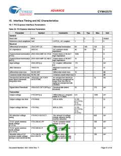
18. Interface Timing and AC Characteristics
18.1 PCI Express Interface Parameters
Table 39. PCI Express Interface Parameters
Parameter
General
Baud rate
Symbol
Comments
Min.
Typ.
Max.
Unit
BPS
–
–
1
5
–
–
–
Gbaud
V
Reference clock amplitude Vref
LVPECL, AC coupled
Receiver
Differential termination
DC impedance
ZRX-DIFF-DC
ZRX-DC
Differential termination
80
40
100
50
120
60
Ω
Ω
DC common-mode
impedance
Powereddowntermination ZRX-HIGH-IMP-DC-POS Power-down or RESET
(POS) high impedance
100k
1k
–
–
–
–
–
–
–
–
Ω
Powereddowntermination ZRX-HIGH-IMP-DC-NEG Power-down or RESET
Ω
(NEG)
high impedance
Input voltage
VRX-DIFFp-p
TRX-EYE
AC coupled, differential
p-p
175
0.4
10
mV
UI
Jitter tolerance
Minimum receiver eye
width
Differential return loss
RLRX-DIFF
Differential return loss
–
–
–
–
dB
dB
ms
Common-mode return loss RLRX-CM
Common-mode return loss 6
–
Unexpected electrical idle TRX-IDEL-DET-DIFF-
An unexpected electrical
idle must be recognized no
longer than this time to
signal an unexpected idle
condition.
–
10
enter detect threshold
integration time
ENTERTIME
Signal detect threshold
VRX-IDLE-DET-DIFFp-p Electrical idle detect
threshold
65
–
175
mV
Transmitter
Output voltage
VTX-DIFFp-p
VTX-RISE
Differential p-p, program- 0.8
mable in 16 steps
–
–
1200
–
mV
UI
Output voltage rise time
Output voltage fall time
20% to 80%
0.125
(2.5 GT/s)
0.15
(5 GT/s)
VTX-FALL
80% to 20%
0.125
–
–
UI
(2.5 GT/s)
0.15
(5 GT/s)
RX detection voltage
swing
VTX-RCV-DETECT
VTX-CM-AC-PP
VTX-CM-AC-P
The amount of voltage
change allowed during
receiver detection.
–
–
–
0
–
–
–
–
600
100
20
mV
mV
mV
mV
TX AC peak common-
mode voltage
(5 GT/s)
TX AC common mode
voltage (5 GT/s)
TX AC peak common-
mode voltage
(2.5 GT/s)
TX AC common mode
voltage (2.5 GT/s)
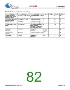
Absolute delta of DC
common-model voltage
during L0 and electrical idle
VTX-CM-DC-ACTIVE-
IDLE-DELTA
Absolute delta of DC
common-model voltage
during L0 and electrical
idle.
100
Document Number: 002-15054 Rev. *I
Page 81 of 94

 CYPRESS [ CYPRESS ]