latched and must remain active until serviced.
C.4.4 Interrupt Latency
Interrupt response time depends on the current state of the 8051. The fastest response time is 5
instruction cycles: 1 to detect the interrupt, and 4 to perform the LCALLto the ISR.
The maximum latency (13 instruction cycles) occurs when the 8051 is currently executing a
RETIinstruction followed by a MULor DIVinstruction. The 13 instruction cycles in this case
are: 1 to detect the interrupt, 3 to complete the RETI, 5 to execute the DIVor MUL, and 4 to
execute the LCALLto the ISR. For the maximum latency case, the response time is 13 x 4 =
52 CLK24 cycles.
C.4.5 Single-Step Operation
The 8051 interrupt structure provides a way to perform single-step program execution. When
exiting an ISR with an RETIinstruction, the 8051 will always execute at least one instruction
of the task program. Therefore, once an ISR is entered, it cannot be re-entered until at least
one program instruction is executed.
To perform single-step execution, program one of the external interrupts (for example,INT0)
to be level-sensitive and write an ISR for that interrupt the terminates as follows:
JNB TCON.1,$
; wait for high on INT0# pin
; wait for low on INT0# pin
; return for ISR
JB
TCON.1,$
RETI
The CPU enters the ISR when the INT0# pin goes low, then waits for a pulse on INT0#. Each
time INT0# is pulsed, the CPU exits the ISR, executes one program instruction, then re-enters
the ISR.
C.5
Reset
The 8051 RESET pin is internally connected to an EZ-USB register bit that is controllable
through the USB host. See Chapter 10, "EZ-USB Resets" for details.
C.6
Power Saving Modes
C.6.1 Idle Mode
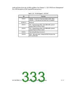
An instruction that sets the IDLE bit (PCON.0) causes the 8051 to enter idle mode when that
instruction completes. In idle mode, CPU processing is suspended, and internal registers
maintain their current data. When the 8051 core is in idle, the EZ-USB core enters suspend
C - 36
Appendix C: 8051 Hardware Description
EZ-USB TRM v1.9

 CYPRESS [ CYPRESS ]