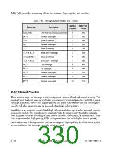
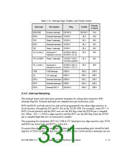
Table C-19. Interrupt Flags, Enables, and Priority Control
Priority
Control
Interrupt
Description
Flag
EICON.4
Enable
RESUME
INT0
Resume interrupt
EICON.5
IE.0
N/A
IP.0
IP.1
IP.2
IP.3
IP.4
External interrupt 0 TCON.1
Timer 0 interrupt TCON.5
External interrupt 1 TCON.3
TF0
IE.1
INT1
IE.2
TF1
Timer 1 interrupt
Serial port 0
TCON.7
IE.3
TI_0 or RI_0
SCON0.0 (RI.0),
IE.4
transmit or receive SCON0.1 (Ti_0)
TF2 or EXF2 Timer 2 interrupt
T2CON.7 (TF2),
T2CON.6 (EXF2)
IE.5
IE.6
IP.5
IP.6
TI_1 or RI_1
Serial port 1
SCON1.0 (RI_1),
transmit or receive SCON1.1 (TI_1)
USB
I2C
USB interrupt
I2C interrupt
EXIF.4
EXIT.5
EIE.0
EIE.1
EIE.2
EIE.3
EIE.4
EIP.0
EIP.1
EIP.2
EIP.3
EIP.4
INT4
INT5
INT6
External interrupt 4 EXIF.6
External interrupt 5 EXIF.7
External INT 6
EICON.3
C.4.3 Interrupt Sampling
The internal timers and serial ports generate interrupts by setting their respective SFR
interrupt flag bits. External interrupts are sampled once per instruction cycle.
INT0 and INT1 are both active low and can be programmed to be either edge-sensitive or
level-sensitive, through the IT0 and IT1 bits in the TCON SFR. For example, when IT0 = 0,
INT0 is level-sensitive and the 8051 core sets the IE0 flag when the INT0# pin is sampled
low. When IT0 = 1, INT0 is edge-sensitive and the 8051 sets the IE0 flag when the INT0#
pin is sampled high then low on consecutive samples.
The remaining five interrupts (INT 4-6, USB & I2C Interrupts) are edge-sensitive only. INT6
and INT4 are active high and INT5 is active low.
To ensure that edge-sensitive interrupts are detected, the corresponding ports should be held
high for 4 CLK24 cycles and then low for 4 CLK24 cycles. Level-sensitive interrupts are not
EZ-USB TRM v1.9
Appendix C: 8051 Hardware Description
C - 35

 CYPRESS [ CYPRESS ]