machine cycle after the 8th bit is shifted in, the RI_0 (or RI_1) bit is set and reception stops
until the software clears the RI bit.
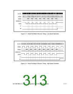
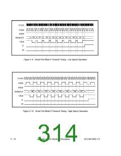
Figure C-7.through Figure C-10.illustrate Serial Port Mode 0 transmit and receive timing for
both low-speed (CLK24/12) and high-speed (CLK24/4) operation.
Table C-8. SCON0 Register - SFR 98h
Bit
Function
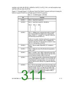
SCON0.7
SCON0.6
SM0_0 - Serial Port 0 mode bit 0.
SM1_0 - Serial Port 0 mode bit 1, decoded as:
SM0_0 SM1_0 Mode
0
0
1
1
0
1
0
1
0
1
2
3
SCON0.5
SM2_0 - Multiprocessor communication enable. In modes 2
and 3, this bit enables the multiprocessor communication
feature. If SM2_0 = 1 in mode 2 or 3, then RI_0 will not be
activated if the received 9th bit is 0.
If SM2_0=1 in mode 1, then RI_0 will only be activated if a
valid stop is received. In mode 0, SM2_0 establishes the
baud rate: when SM2_0=0, the baud rate is CLK24/12; when
SM2_0=1, the baud rate is CLK24/4.
SCON0.4
SCON0.3
SCON0.2
REN_0 - Receive enable. When REN_0=1, reception is
enabled.
TB8_0 - Defines the state of the 9th data bit transmitted in
modes 2 and 3.
RB8_0 - In modes 2 and 3, RB8_0 indicates the state of the
9th bit received. In mode 1, RB8_0 indicates the state of the
received stop bit. In mode 0, RB8_0 is not used.
SCON0.1
SCON0.0
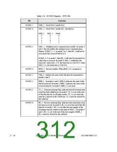
TI_0 - Transmit interrupt flag. indicates that the transmit data
word has been shifted out. In mode 0, TI_0 is set at the end
of the 8th data bit. In all other modes, TI_0 is set when the
stop bit is placed on the TXD0 pin. TI_0 must be cleared by
firmware.
RI_0 - Receive interrupt flag. Indicates that serial data word
has been received. In mode 0, RI_0 is set at the end of the 8th
data bit. In mode 1, RI_0 is set after the last sample of the
incoming stop bit, subject to the state of SM2_0. In modes 2
and 3, RI_0 is set at the end of the last sample of RB8_0.
RI_0 must be cleared by firmware.
EZ-USB TRM v1.9
Appendix C: 8051 Hardware Description
C - 15

 CYPRESS [ CYPRESS ]