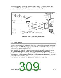
The counter time base in baud rate generator mode is CLK24/2. To use an external clock
source, set C/T2 to 1 and apply the desired clock source to the T2 pin.
TIMER 1 OVERFLOW
CLK24
Divide
by 2
0
Divide
by 2
C/T2
CLK
1
SMOD1
0
1
T2 pin
TR2
RX
CLOCK
RCLK
7
8
0
0
15
15
TL2
TH2
0
1
Divide
by 16
TCLK
RCAP2L
RCAP2H
0
1
7 8
Divide
by 16
EXEN2
TIMER 2 INTERRUPT
EXF2
TX
CLOCK
T2EX pin
Figure C-6. Timer 2 - Baud Rate Generator Mode
C.3
Serial Interface
The 8051 core provides two serial ports. Serial Port 0 is identical in operation to the standard
8051 serial port. Serial Port 1 is identical to Serial Port 0, except that Timer 2 cannot be used
as the baud rate generator for Serial Port 1.
Each serial port can operate in synchronous or asynchronous mode. In synchronous mode,
8051 generates the serial clock and the serial port operates in half-duplex mode. In
asynchronous mode, the serial port operates in full-duplex mode. In all modes, 8051 buffers
received data in a holding register, enabling the UART to receive an incoming byte before the
software has read the previous value.
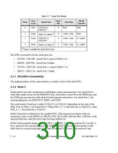
Each serial port can operate in one of four modes, as outlined in Table C-7..
EZ-USB TRM v1.9
Appendix C: 8051 Hardware Description
C - 13

 CYPRESS [ CYPRESS ]