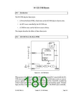
connected to Vcc through a 1 µF capacitor and to GND through a 10-K resistor
(Figure 10-1). The oscillator and PLL are unaffected by the state of the RESET pin.
The CLK24 signal is active while RESET = HI. When RESET returns LO, the activity on
the CLK24 pin depends on whether or not the EZ-USB chip is in suspend state. If in sus-
pend, CLK24 stops. Resumption of USB bus activity or asserting the WAKEUP# pin LO
re-starts the CLK24 signal.
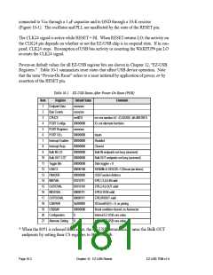
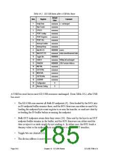
Power-on default values for all EZ-USB register bits are shown in Chapter 12, "EZ-USB
Registers." Table 10-1 summarizes reset states that affect USB device operation. Note
that the term “Power-On Reset” refers to a reset initiated by application of power, or by
assertion of the RESET pin.
Table 10-1. EZ-USB States After Power-On Reset (POR)
Item
1
Register
Endpoint Data
Byte Counts
CPUCS
Default Value
xxxxxxxx
xxxxxxxx
rrrr0011
Comment
2
3
rrrr=rev number, b1 =CLK24OE, b0=8051RES
IO, not alternate functions
4
PORT Configs
PORT Registers
PORT OEs
00000000
xxxxxxxx
00000000
00000000
00000000
00000000
00000000
00000000
00000100
00000000
01010111
01010101
00000111
00000111
0x000000
00000000
0
5
6
Inputs
7
Interrupt Enables
Interrupt Reqs
Bulk IN C/S
Disabled
8
Cleared
9
Bulk IN endpoints not busy (unarmed)
Bulk OUT endpoints not busy (unarmed)
Data toggles = 0
10 Bulk OUT C/S*
11 Toggle Bits
12 USBCS
RENUM=0, DISCOE=1 (Discon pin drives)
USB Function Address
EP0,1,2,4,6 IN valid
13 FNADDR
14 IN07VAL
15 OUT07VAL
16 INISOVAL
17 OUTISOVAL
18 USBPAIR
19 USBBAV
EP0,2,4,6 OUT valid
EP8,9,10 IN valid
EP8,910OUT valid
ISOsend0 (b7) = 0, no pairing
Break condition cleared, no Autovector
Internal EZ-USB core value
Internal EZ-USB core value
20 Configuration
21 Alternate Setting
0
* When the 8051 is released from reset, the EZ-USB automatically arms the Bulk OUT
endpoints by setting their CS registers to 000000010b.
Page 10-2
Chapter 10. EZ-USB Resets
EZ-USB TRM v1.9

 CYPRESS [ CYPRESS ]