8.2
Isochronous IN Transfers
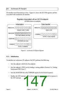
IN transfers travel from device to host. Figure 8-2 shows the EZ-USB registers and bits
associated with isochronous IN transfers.
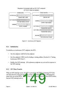
Registers Associated with an ISO IN endpoint
(EP8IN shown as example)
Initialization
Data transfer
15 14 13 12 11 10
9
8
7
6
5
4
3
2
1
1
0
0
INISOVAL
IN8ADDR
USBPAIR
USBIEN
IN8DATA
USBIRQ
Endpoint Valid (1=valid)
Data to USB
A9 A8 A7 A6 A5 A4
0
0
7
6
5
4
3
2
FIFO Start Address (see text)
SOFIR (1=clear request)
7
6
5
4
3
2
1
0
ISOSEND0 (see text)
7
6
5
4
3
2
1
0
SOFIE (1=enabled)
Figure 8-2. Isochronous IN Endpoint Registers
8.2.1 Initialization
To initialize an isochronous IN endpoint, the 8051 performs the following:
•
•
Sets the endpoint valid bit for the endpoint.
Sets the endpoint’s FIFO size by loading a starting address (Section 8.4, "Setting
Isochronous FIFO Sizes").
•
•
Sets the ISOSEND0 bit in the USBPAIR register for the desired response.
Enables the SOF interrupt. All isochronous endpoints are serviced in response to
the SOF interrupt.
Page 8-2
Chapter 8. EZ-USB CPU
EZ-USB TRM v1.9

 CYPRESS [ CYPRESS ]