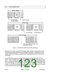
The STATUS stage consists of an empty data packet with the opposite direction of the data
stage, or an IN if there was no data stage. This empty data packet gives the device a
chance to ACK or NAK the entire CONTROL transfer. The 8051 writes a “1” to a bit call
HSNAK (Handshake NAK) to clear it and instruct the EZ-USB core to ACK the STATUS
stage.
The HSNAK bit is used to hold off completing the CONTROL transfer until the device
has had time to respond to a request. For example, if the host issues a Set_Interface
request, the 8051 performs various housekeeping chores such as adjusting internal modes
and re-initializing endpoints. During this time the host issues handshake (STATUS stage)
packets to which the EZ-USB core responds with NAKs, indicating “busy.” When the
8051 completes the desired operation, it sets HSNAK=1 (by writing a “1” to the bit) to ter-
minate the CONTROL transfer. This handshake prevents the host from attempting to use
a partially configured interface.
To perform an endpoint stall for the DATA or STATUS stage of an endpoint zero transfer
(the SETUP stage can never stall), the 8051 must set both the STALL and HSNAK bits for
endpoint zero.
Some CONTROL transfers do not have a DATA stage. Therefore the 8051 code that pro-
cesses the SETUP data should check the length field in the SETUP data (in the 8-byte
buffer at SETUPDAT) and arm endpoint zero for the DATA phase (by loading IN0BC or
OUT0BC) only if the length is non-zero.
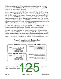
Two 8051 interrupts provide notification that a SETUP packet has arrived, as shown in
Figure 7-2.
SETUP Stage
S
E
T
U
P
D
A
T
A
0
C
R
C
1
A
D
D
R
E
N
D
P
C
R
C
5
SETUPDAT
8 bytes
Setup
Data
A
C
K
8 RAM
bytes
6
Token Packet
Data Packet
H/S Pkt
SUTOK
Interrupt
SUDAV
Interrupt
Figure 7-2. The Two Interrupts Associated with EP0 CONTROL Transfers
The EZ-USB core sets the SUTOKIR bit (SETUP Token Interrupt Request) when the EZ-
USB core detects the SETUP token at the beginning of a CONTROL transfer. This inter-
rupt is normally used only for debug.
The EZ-USB core sets the SUDAVIR bit (Setup Data Available Interrupt Request) when
the eight bytes of SETUP data have been received error-free and transferred to eight EZ-
EZ-USB TRM v1.9
Chapter 7. EZ-USB CPU
Page 7-3

 CYPRESS [ CYPRESS ]