2.0 Circuit Description
2.8 Transmitter
Bt8370/8375/8376
Fully Integrated T1/E1 Framer and Line Interface
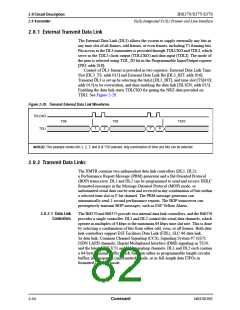
Figure 2-31. Interrupt Driven Transmit Data Link Processing
Main Line Code
Message
Transmit Message
0x00
0x20
0x40
0x60
Block 1
Block 2
Block 3
Block 4
Write Block/Byte to FIFO
Return
Interrupt Service Routine
Interrupt Occurred
Read Interrupt Status
If
Transmit Data
Link Near Empty
Interrupt
No
Yes
Write Block/Byte to FIFO
Process Other Interrupt
Return
If
No
End of
Message
Yes
Write End of Message Register
Return
Return
Bt8370/8375/8376 uses a hierarchical interrupt structure, with 1 top-level
Interrupt Request register [IRR; addr 003] directing software to the lower levels.
Of all the interrupt sources, the 2 most significant bandwidth requirements are
signaling and data link interrupts. Each data link controller has a top-level
interrupt status register that reports data link operations (see Data Link 1 and 2
Interrupt Status registers [ISR2; addr 009, and ISR1; 00A]). The processor uses a
2-step interrupt scheme for the data link: it reads the Interrupt Request register,
then uses that register value to read the corresponding Data Link Interrupt Status
register.
2-58
Conexant
N8370DSE

 CONEXANT [ CONEXANT SYSTEMS, INC ]