9. Schematic __________________________________________________________ 20
10. Component layout___________________________________________________ 21
Table of Figures
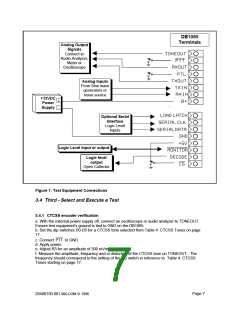
FIGURE 1: TEST EQUIPMENT CONNECTIONS
7
10
11
12
13
19
20
21
22
FIGURE 2: COMPOSITE TEST SIGNAL CIRCUIT DIAGRAM
FIGURE 3: TESTING AT DIFFERENT SUPPLY VOLTAGES
FIGURE 4: SUPPLY VOLTAGE VS TYPICAL SUPPLY CURRENT
FIGURE 5: BREAKING OUT SMALL CIRCUIT
FIGURE 6: COMPARISON OF EXTERNAL COMPONENTS FOR OLDER CTCSS ICS
FIGURE 7: DB1065 SCHEMATIC
FIGURE 8: COMPONENT VIEW ASSEMBLY DRAWING
FIGURE 9: SOLDER VIEW ASSEMBLY DRAWING
1. General Information
1.1 Introduction
This manual provides general information to support the installation and operation of the DB1065
Development Kit, a complete test platform to demonstrate and test the MX465 CTCSS encoder/
decoder.
All trademarks and service marks are held by their respective owners.
1.2 Warranty
The DB1065 hardware has been developed and is provided to help designers develop designs
based on the MX465 CTCSS Encoder / Decoder IC. Every reasonable effort has been made to
provide high quality and performance in pursuit of that goal.
Toward that end, MX-COM, Inc. would value any suggestions to improve the DB1065’s manual
and suggestions concerning the DB1065’s hardware design.
Since experiments and designs are the responsibility of the DB1065 user, MX-COM, Inc.’s liability
regarding the use of the DB1065 is in all cases limited to the DB1065 purchase price.
No other warranty is expressed or implied.
Page 3
20480150.001 MX-COM ꢀ 1996

 CMLMICRO [ CML MICROCIRCUITS ]