RF Quadrature Transceiver / RF Quadrature Receiver
CMX991/CMX992
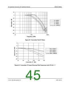
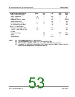
8.1.3.2
AC Parameters – Receiver Sections
Rx 1st Mixer
Notes
Min.
Typ.
Max.
Units
Gain
1, 7, 7b
–
18
–
dB(V/V)
Noise Figure
7, 6b
–
11.5
–
dB
Input Third Order Intercept Point (IIP3)
450MHz
7, 7a
+9.5
+8
100
50
–
+11
+9.5
–
–
–
dBm
dBm
MHz
MHz
Ω
950MHz
7, 7a
Input Frequency Range
LO Frequency Range
Input Impedance
9
3
8
1000
1150
–
–
300
–
IF Output Frequency Range
IF Output Impedance
10
–
150
–
MHz
Ω
500 ║
4pF
LO Leakage at Input (fLO/2)
150MHz Operation
460MHz Operation
950MHz Operation
1dB Compression Point (input)
Half IF Rejection
Blocking
6
6a
6b
6c
–
–
-99
-92
-84
-7
–
–
–
–
–
–
dB
dB
–
dB
-10
60
–
dBm
dB
2, 4
5, 6
70
90
dB
LO Input
Frequency Range
Input Level
100
-10
–
–
–
2000
MHz
dBm
0
Division Ratios
1, 2 or 4
–
Notes:
1. Measured from a low loss matched input source to a matched output load.
2. Significant variation in half IF rejection can occur as a function of frequency and LO
level/matching. Users are recommended to optimise for a particular application.
3. LO as supplied to mixer circuit block.
4. Relative level of signal at mixer IF output relative to RF signal of –30dBm; IF = 45MHz
and RF = 450MHz or 800MHz.
5. Relative to –107dBm (level from ETSI EN 300 113), based on IF = 45MHz and RF =
450MHz, to give ~3dB rise in mixer output noise floor.
6. Including operation of selectable dividers, tested in divide by 2 mode.
6a fLO = 390MHz at –5dBm, 45MHz IF, Circuit matched for 155MHz input (Table 15)
6b fLO = 1010MHz at –5dBm, 45MHz IF, Circuit matched for 455MHz input (Table 4)
6c fLO = 1810MHz at –5dBm, 45MHz IF, Circuit matched for 950MHz input (Table 15)
7. Gain, IP3 and noise figure can be adjusted using external resistors
(R1 and R2 in Figure 6).
7a. Measured as a system from mixer input to I/Q output (pins RXIN, RXIP, RXQN, RXQP)
and using the circuits of Figure 6 and Figure 7.
7b. Mixer gain is the defined as 20log10(Vin/Vout) + Lmatch. where Vin = voltage at 50 ohm input to
mixer stage (‘Input’ in Figure 6); Vout = voltage at mixer output (MIXOUT1 or MIXOUT2);
Lmatch = loss of input matching components (e.g. T1 in Figure 6).
8. There is also an internal series capacitance to each mixer input of nominally 8pF.
9. The mixer can be used below 100MHz with reduced performance (see separate
application note available from the CML website).
2012 CML Microsystems Plc
49
D/991_992/18

 CMLMICRO [ CML MICROCIRCUITS ]