CS8900A
Crystal LAN™ Ethernet Controller
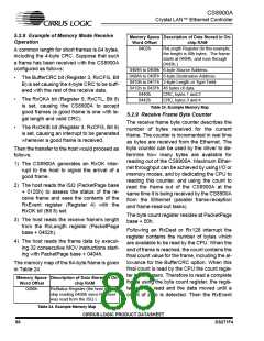
5.2.8 Example of Memory Mode Receive
Operation
Memory Space Description of Data Stored in On-
Word Offset
chip RAM
0402h
RxLength Register (In this example,
the length is 40h bytes. The frame
starts at 0404h, and runs through
0443h.)
A common length for short frames is 64 bytes,
including the 4-byte CRC. Suppose that such
a frame has been received with the CS8900A
configured as follows:
0404h to 0409h 6-byte Source Address.
040Ah to 040Fh 6-byte Destination Address.
0410h to 0411h 2-byte Length or Type Field.
0412h to 043Fh 46 bytes of data.
•
The BufferCRC bit (Register 3, RxCFG, Bit
B) is set causing the 4-byte CRC to be buff-
ered with the rest of the receive data.
0440h
0442h
CRC, bytes 1 and 2
CRC, bytes 3 and 4
•
The RxOKA bit (Register 5, RxCTL, Bit 8)
is set, causing the CS8900A to accept
good frames (a good frame is one with le-
gal length and valid CRC).
Table 24. Example Memory Map
5.2.9 Receive Frame Byte Counter
The receive frame byte counter describes the
number of bytes received for the current
frame. The counter is incremented in real time
as bytes are received from the Ethernet. The
byte counter can be used by the driver to de-
termine how many bytes are available for
reading out of the CS8900A. Maximum Ether-
net throughput can be achieved by using I/O or
memory modes, and by dedicating the CPU to
reading this counter, and using the count to
read the frame out of the CS8900A at the
same time it is being received by the CS8900A
from the Ethernet (parallel frame-reception
and frame-read-out tasks).
•
The RxOKiE bit (Register 3, RxCFG, Bit 8)
is set, causing an interrupt to be generated
whenever a good frame is received.
Then the transfer to the host would proceed as
follows:
1) The CS8900A generates an RxOK inter-
rupt to the host to signal the arrival of a
good frame.
2) The host reads the ISQ (PacketPage base
+ 0120h) to assess the status of the re-
ceive frame and sees the contents of the
RxEvent register (Register 4) with the
RxOK bit (Bit 8) set.
The byte count register resides at PacketPage
base + 50h.
3) The host reads the receive frame's length
from the RxLength register (PacketPage
base + 0402h).
Following an RxDest or Rx128 interrupt the
register contains the number of bytes which
are available to be read by the CPU. When the
end of frame is reached, the count contains the
final count value for the frame, including the al-
lowance for the BufferCRC option. When this
final count is read by the CPU the count regis-
ter is set to zero. Therefore to read a complete
frame using the byte count register, the regis-
ter can be read and the data moved until a
count of zero is detected. Then the RxEvent
4) The host reads the frame data by execut-
ing 32 consecutive MOV instructions start-
ing with PacketPage base + 0404h.
The memory map of the 64-byte frame is given
in Table 24.
Memory Space Description of Data Stored in On-
Word Offset
chip RAM
0400h
RxStatus Register (the host may
skip reading 0400h since RxEvent
was read from the ISQ.)
Table 24. Example Memory Map
CIRRUS LOGIC PRODUCT DATASHEET
86
DS271F4

 CIRRUS [ CIRRUS LOGIC ]