CS8900A
Crystal LAN™ Ethernet Controller
(for a ’C56, ’CS56, ’C66 or ’CS66), are shifted 3.6.1 Accessing the Boot PROM
out of the CS8900A, into the EEPROM. If the
command is a Write, the data in the EEPROM
Data register (PacketPage base + 0042h) fol-
lows. If the command is a Read, the data in the
specified EEPROM location is written into the
EEPROM Data register. If the command is an
Erase or Erase-All, no data is transferred to or
from the EEPROM Data register. Before issu-
ing any command, the host must wait for the
SIBUSY bit (Register 16, SelfST, bit 8) to
clear. After each command has been issued,
the host must wait again for SIBUSY to clear.
To retrieve the data stored in the Boot PROM,
the host issues a Read command to the Boot
PROM as a Memory space access. The
CS8900A decodes the command and drives
the CSOUT pin low, causing the data stored in
the Boot PROM to be shifted into the bus
transceiver. The bus transceiver then drives
the data out onto the ISA bus.
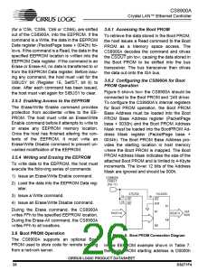
3.6.2 Configuring the CS8900A for Boot
PROM Operation
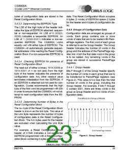
Figure 6 shows how the CS8900A should be
connected to the Boot PROM and ’245 driver.
To configure the CS8900A’s internal registers
for Boot PROM operation, the Boot PROM
Base Address must be loaded into the Boot
PROM Base Address register (PacketPage
base + 0030h) and the Boot PROM Address
Mask must be loaded into the BootPROM Ad-
dress Mask register (PacketPage base +
0034h). The Boot PROM Base Address pro-
vides the starting location in host memory
where the Boot PROM is mapped. The Boot
PROM Address Mask indicates the size of the
attached Boot PROM and is limited to 4-Kbyte
increments. The lower 12 bits of the Address
Mask are ignored and should be 000h.
3.5.3 Enabling Access to the EEPROM
The Erase/Write Enable command provides
protection from accidental writes to the EE-
PROM. The host must write an Erase/Write
Enable command before it attempts to write to
or erase any EEPROM memory location.
Once the host has finished altering the con-
tents of the EEPROM, it must write an
Erase/Write Disable command to prevent un-
wanted modification of the EEPROM.
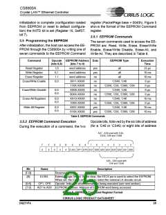
3.5.4 Writing and Erasing the EEPROM
To write data to the EEPROM, the host must
execute the following series of commands:
1) Issue an Erase/Write Enable command.
C S8900A
C SO U T
(Pin 17)
2) Load the data into the EEPROM Data reg-
ister.
27C 256
CE
OE
74LS245
OE
3) Issue a Write command.
20
22
19
4) Issue an Erase/Write Disable command.
DIR
A1
.
.
.
During the Erase command, the CS8900A
writes FFh to the specified EEPROM location.
During the Erase-All command, the CS8900A
writes FFh to all locations.
B1
.
.
.
ISA
BUS
SA(0:14)
SD(0:7)
A8
B8
3.6 Boot PROM Operation
Figure 6. Boot PROM Connection Diagram
The CS8900A supports an optional Boot
PROM used to store code for remote booting
from a network server.
In the EEPROM example shown in Table 7,
the Boot PROM starting address is D0000h
CIRRUS LOGIC PRODUCT DATASHEET
26
DS271F4

 CIRRUS [ CIRRUS LOGIC ]