CS8900A
Crystal LAN™ Ethernet Controller
bytes of configuration data are stored in the
Reset Configuration Block.
data. This Reset Configuration Block occupies
6 bytes (3 words) of EEPROM space (2 bytes
for the header and 4 bytes of configuration da-
ta).
3.4.3.3 Determining the EEPROM Type
The LSB of the high byte of the header indi-
cates the type of EEPROM attached: sequen-
tial or non-sequential. An LSB of 0 (XXXX-
XXX0) indicates a sequential EEPROM. An
LSB of 1 (XXXX-XXX1) indicates a non-se-
quential EEPROM. The CS8900A works
3.4.4 Groups of Configuration Data
Configuration data are arranged as groups of
words. Each group contains one or more
words of data that are to be loaded into Pack-
etPage registers. The first word of each group
equally well with either type of EEPROM. The is referred to as the Group Header. The Group
CS8900A will automatically generate sequen- Header indicates the number of words in the
tial addresses while reading the Reset Config- group and the address of the PacketPage reg-
uration Block if a non-sequential EEPROM is
used.
ister into which the first data word in the group
is to be loaded. Any remaining words in the
group are stored in successive PacketPage
registers.
3.4.3.4 Checking EEPROM for presence of
Reset Configuration Block
3.4.4.1 Group Header
The read-out of either a binary 101X-XXX0 or
101X-XXX1 (X = do not care) from the high
byte of the header indicates the presence of
configuration data. Any other readout value
terminates initialization from the EEPROM. If
an EEPROM is attached but not used for con-
figuration, Crystal recommends that the high
byte of the first word be programmed with 00h
in order to ensure that the CS8900A will not at-
tempt to read configuration data from the EE-
PROM.
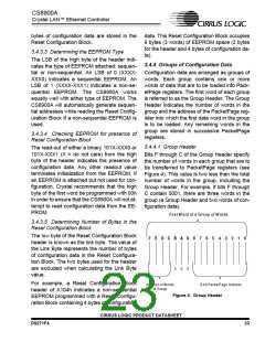
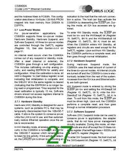
Bits F through C of the Group Header specify
the number of words in each group that are to
be transferred to PacketPage registers (see
Figure 4). This value is two less than the total
number of words in the group, including the
Group Header. For example, if bits F through
C contain 0001, there are three words in the
group (a Group Header and two words of con-
figuration data).
First W ord of a G roup of W ords
3.4.3.5 Determining Number of Bytes in the
Reset Configuration Block
The low byte of the Reset Configuration Block
header is known as the link byte. The value of
the Link Byte represents the number of bytes
of configuration data in the Reset Configura-
tion Block. The two bytes used for the header
are excluded when calculating the Link Byte
value.
F
E
D
C
B
A
9
8
7
6
5
4
3
2
1
0
0
0
0
For example, a Reset Configuration Block
header of A104h indicates a non-sequential
EEPROM programmed with a Reset Configu-
ration Block containing 4 bytes of configuration
Num ber of W ords
in Group
9-bit PacketPage Address
Figure 4. Group Header
CIRRUS LOGIC PRODUCT DATASHEET
DS271F4
23

 CIRRUS [ CIRRUS LOGIC ]