CS8900A
Crystal LAN™ Ethernet Controller
as Memory space operations, I/O space oper-
ations, or as DMA operations using host DMA.
Also, the CS8900A provides the capability to
switch between Memory or I/O operation and
DMA operation by using Auto-Switch DMA
and StreamTransfer.
I/O locations in the host system’s I/O space.
I/O Mode is the default configuration for the
CS8900A and is always enabled.
For an I/O Read or Write operation, the AEN
pin must be low, and the 16-bit I/O address on
the ISA System Address bus (SA0 - SA15)
must match the address space of the
CS8900A. For a Read, IOR must be low, and
for a Write, IOW must be low.
The Section 5.2 on page 78 through
Section 5.5 on page 96 provide a detailed de-
scription of packet reception.
For additional information about I/O Mode, see
Section 4.10 on page 75.
3.2 ISA Bus Interface
The CS8900A provides a direct interface to
ISA buses running at clock rates from 8 to 11
MHz. Its on-chip bus drivers are capable of de-
livering 24 mA of drive current, allowing the
CS8900A to drive the ISA bus directly, without
added external “glue logic”.
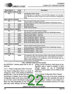
3.2.3 Interrupt Request Signals
The CS8900A has four interrupt request out-
put pins that can be connected directly to any
four of the ISA bus Interrupt Request signals.
Only one interrupt output is used at a time. It is
selected during initialization by writing the in-
terrupt number (0 to 3) into PacketPage Mem-
ory base + 0022h. Unused interrupt request
pins are placed in a high-impedance state.
The selected interrupt request pin goes high
when an enabled interrupt is triggered. The pin
goes low after the Interrupt Status Queue
(ISQ) is read as all 0’s (see Section 5.1 on
page 78 for a description of the ISQ).
The CS8900A is optimized for 16-bit data
transfers, operating in either Memory space,
I/O space, or as a DMA slave.
Note that ISA-bus operation below 8 MHz
should use the CS8900A’s Receive DMA
mode to minimize missed frames. See
Section 5.3 on page 90 for a description of Re-
ceive DMA operation.
3.2.1 Memory Mode Operation
Table 2 presents one possible way of connect-
ing the interrupt request pins to the ISA bus
that utilizes commonly available interrupts and
facilitates board layout.
When configured for Memory Mode operation,
the CS8900A’s internal registers and frame
buffers are mapped into a contiguous 4-Kbyte
block of host memory, providing the host with
direct access to the CS8900A’s internal regis-
ters and frame buffers. The host initiates Read
operations by driving the MEMR pin low and
Write operations by driving the MEMW pin low.
CS8900A Interrupt
Request Pin
ISA Bus
Interrupt
PacketPage
base + 0022h
INTRQ3 (Pin 35)
INTRQ0 (Pin 32)
INTRQ1 (Pin 31)
INTRQ2 (Pin 30)
IRQ5
IRQ10
IRQ11
IRQ12
0003h
0000h
0001h
0002h
For additional information about Memory
Mode, see Section 4.9 on page 73.
Table 2. Interrupt Assignments
3.2.2 I/O Mode Operation
3.2.4 DMA Signals
When configured for I/O Mode operation, the
CS8900A is accessed through eight, 16-bit I/O
ports that are mapped into sixteen contiguous
The CS8900A interfaces directly to the host
DMA controller to provide DMA transfers of re-
ceive frames from CS8900A memory to host
CIRRUS LOGIC PRODUCT DATASHEET
18
DS271F4

 CIRRUS [ CIRRUS LOGIC ]