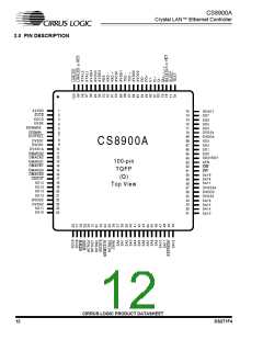
CS8900A
Crystal LAN™ Ethernet Controller
General Pins
XTAL[1:2] - Crystal, Input/Output PINS 97 and 98.
A 20 MHz crystal should be connected across these pins. If a crystal is not used, a 20
MHz signal should be connected to XTAL1 and XTAL2 should be left open. (See
Section 7.3 on page 112 and Section 7.7 on page 122.)
SLEEP - Hardware Sleep, Input Internal Weak Pullup PIN 77.
Active-low input used to enable the two hardware sleep modes: Hardware Suspend
and Hardware Standby. (See Section 3.7 on page 27.)
LINKLED or HC0 - Link Good LED or Host Controlled Output 0, Open Drain Output PIN
99.
When the HCE0 bit of the Self Control register (Register 15) is clear, this active-low
output is low when the CS8900A detects the presence of valid link pulses. When the
HC0E bit is set, the host may drive this pin low by setting the HCBO in the Self
Control register.
BSTATUS or HC1 - Bus Status or Host Controlled Output 1, Open Drain Output PIN 78.
When the HC1E bit of the Self Control register (Register 15) is clear, this active-low
output is low when receive activity causes an ISA bus access. When the HC1E bit is
set, the host may drive this pin low by setting the HCB1 in the Self Control register.
LANLED - LAN Activity LED, Open Drain Output PIN 100.
During normal operation, this active-low output goes low for 6 ms whenever there is a
receive packet, a transmit packet, or a collision. During Hardware Standby mode, this
output is driven low when the receiver detects network activity.
TEST - Test Enable, Input Internal Weak Pullup PIN 76.
Active-low input used to put the CS8900A in Boundary Scan Test mode. For normal
operation, this pin should be high.
RES - Reference Resistor, Input PIN 93.
This input should be connected to a 4.99KΩ ± 1% resistor needed for biasing of
internal analog circuits.
DVDD[1:4] - Digital Power, Power PINS 9, 22, 56, and 69.
Provides 5 V ± 5% power to the digital circuits of the CS8900A.
DVSS[1:4} and DVSS1A, DVSS3A - Digital Ground, Ground PINS 8, 10, 23, 55, 57, and
70.
Provides ground reference (0 V) to the digital circuits of the CS8900A.
AVDD[1:3] - Analog Power, Power PINS 90, 85, and 95.
Provides 5 V ± 5% power to the analog circuits of the CS8900A.
AVSS[0:4] - Analog Ground, Ground PINS 1, 89, 86, 94, 96.
Provide ground reference (0 V) to the analog circuits of the CS8900A.
CIRRUS LOGIC PRODUCT DATASHEET
16
DS271F4

 CIRRUS [ CIRRUS LOGIC ]