CS5463
9. BASIC APPLICATION CIRCUITS
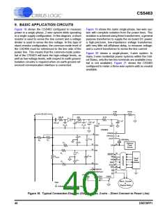
Figure 18 shows the CS5463 configured to measure
power in a single-phase, 2-wire system while operating
in a single-supply configuration. In this diagram, a shunt
resistor is used to sense the line current and a voltage
divider is used to sense the line voltage. In this type of
shunt-resistor configuration, the common-mode level of
the CS5466 must be referenced to the line side of the
power line. This means that the common-mode poten-
tial of the CS5463 will track the high-voltage levels, as
well as low-voltage levels, with respect to earth ground.
Isolation circuitry is required when an earth-ground-ref-
erenced communication interface is connected.
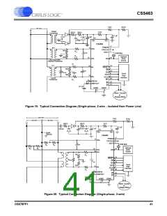
Figure 19 shows the same single-phase, two-wire sys-
tem with complete isolation from the power lines. This
isolation is achieved using three transformers: a general
purpose transformer to supply the on-board DC power;
a high-precision, low-impedance voltage transformer,
with very little roll-off/phase-delay, to measure voltage;
and a current transformer to sense the line current.
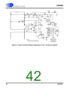
Figure 20 shows a single-phase, 3-wire system. In
many 3-wire residential power systems within the Unit-
ed States, only the two line terminals are available (neu-
tral is not available). Figure 21 shows the CS5463
configured to meter a three-wire system with no neutral
available.
Ω
5 k
10 kΩ
120 VAC
N
L
Ω
Ω
10
500
500
0.1 µF
470 µF
0.1 µF
470 nF
14
VA+
3
VD+
CS5463
17
2
PFMON
CPUCLK
XOUT
9
VIN+
CV-
1
CVdiff
4.096 MHz
R
R
1
2
C
V+
RV-
Optional
Clock
Source
10
15
24
VIN-
IIN-
XIN
C I-
CI+
RI-
19
7
RESET
CS
CIdiff
RShunt
Serial
Data
Interface
23
6
SDI
RI+
SDO
SCLK
INT
16
5
IIN+
20
12
11
VREFIN
22
21
E2
E1
VREFOUT
0.1 µF
AGND
13
DGND
4
Mech. Counter
Note:
Indicates common (floating) return.
or
Stepper Motor
Figure 18. Typical Connection Diagram (Single-phase, 2-wire – Direct Connect to Power Line)
40
DS678PP1

 CIRRUS [ CIRRUS LOGIC ]