CS49300 Family DSP
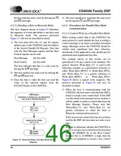
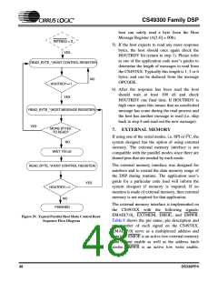
host can safely read a byte from the Host
Message Register (A[1:0] = 00b).
INTREQ = 0
5) If the host expects to read any more response
bytes, the host should once again check the
HOUTRDY bit (return to step 1). Please refer
to one of the application code user’s guides to
determine the length of messages to read from
the CS493XX. Typically this length is 1, 3 or 6
bytes, and can be deduced from the message
OPCODE.
YES
READ_BYTE_*(HOST CONTROL REGISTER)
NO
HOUTRDY==1
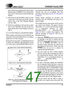
6) After the response has been read the host
should wait at least 100 uS and check
HOUTRDY one final time. If HOUTRDY is
high once again this means that an unsolicited
message has come during the read process and
the host has another message to read (i.e. skip
back to step 4 and read out the new message).
YES
READ_BYTE_*(HOST MESSAGE REGISTER)
YES
MORE BYTES
TO READ?
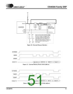
7. EXTERNAL MEMORY
2
If using one of the serial modes, i.e. SPI or I C, the
NO
system designer has the option of using external
memory. The external memory interface is not
compatible with the parallel modes since there are
shared pins that are needed by each mode.
WAIT 100 uS
The external memory interface was designed for
autoboot and to extend the data memory range of
the DSP during runtime. The application user’s
guide for a particular code load will inform the
system designer if memory is required. If no
mention is made of external memory, then external
memory is not required for that application.
READ_BYTE_*(HOST CONTROL REGISTER)
YES
HOUTRDY==1
NO
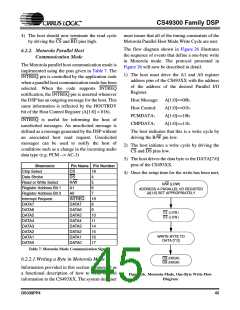
The external memory interface is implemented on
the CS493XX with the following signals:
EMAD[7:0], EXTMEM, EMOE, and EMWR.
Table 8 shows the pin name, pin description and
pin number of each signal on the CS493XX.
EMAD[7:0] serve as a multiplexed address and
data bus. EMOE is an active-low external-memory
data output enable as well as the address latch
strobe. EMWR is an active low write enable.
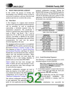
FINISHED
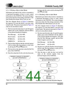
Figure 29. Typical Parallel Host Mode Control Read
Sequence Flow Diagram
48
DS339PP4

 CIRRUS [ CIRRUS LOGIC ]