DAC_DIF2
DAC_DIF1
DAC_DIF0
Description
Format
Figure
0
0
0
0
1
1
1
1
0
0
1
1
0
0
1
1
0
1
0
1
0
1
0
1
0
1
2
3
4
5
6
-
16 on page 34
15 on page 34
17 on page 34
17 on page 34
18 on page 34
19 on page 35
20 on page 35
-
Left Justified, up to 24-bit data
I S, up to 24-bit data
Right Justified, 24-bit data
Right Justified, 16-bit data
One-Line #1, 20-bit
One-Line #2, 24-bit
TDM Mode, 24-bit (slave only)
Reserved
2
Table 12. DAC Digital Interface Formats
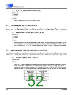
6.5.4 ADC DIGITAL INTERFACE FORMAT (ADC_DIF[2:0])
Default = 110
Function:
These bits select the digital interface format used for the ADC serial port. The required relationship be-
tween the Left/Right clock, serial clock and serial data is defined by the Digital Interface Format and
the options are detailed in the section “CODEC Digital Interface Formats” on page 32. Refer to Table
9. “Serial Audio Interface Channel Allocations” on page 36.
NOTE: The ADC does not meet Quad-Speed Mode timing specifications in the TDM interface format.
ADC_DIF2
ADC_DIF1
ADC_DIF0
Description
Format
Figure
0
0
0
0
1
1
1
1
0
0
1
1
0
0
1
1
0
1
0
1
0
1
0
1
0
1
2
3
4
5
6
-
16 on page 34
15 on page 34
17 on page 34
17 on page 34
18 on page 34
19 on page 35
20 on page 35
-
Left Justified, up to 24-bit data
I S, up to 24-bit data
Right Justified, 24-bit data
Right Justified, 16-bit data
One-Line #1, 20-bit
One-Line #2, 24-bit
TDM Mode, 24-bit (slave only)
Reserved
2
Table 13. ADC Digital Interface Formats
48
DS648PP2

 CIRRUS [ CIRRUS LOGIC ]