The ADC output data is in 2’s complement binary format. For inputs above positive full scale or
below negative full scale, the ADC will output 7FFFFFH or 800000H, respectively and cause the
ADC Overflow bit in the register “Status (address 19h) (Read Only)” on page 54 to be set to a ‘1’.
5.0 V
3.9 V
VA
AINx+
AINx-
2.5 V
2.5 V
1.1 V
3.9 V
1.1 V
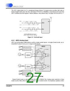
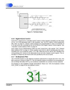
Full-Scale Differential Input Level =
(AINx+) - (AINx-) = 5.6 VPP = 1.98 VRMS
Figure 10. Full-Scale Input
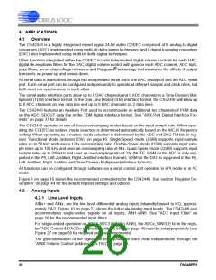
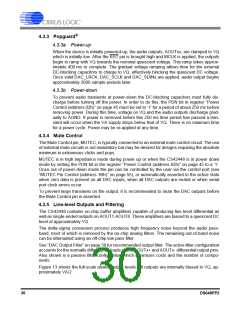
4.2.2 ADC3 Analog Input
ADC3 accommodates differential as well as single-ended inputs. In Single-Ended mode, an in-
ternal MUX selects from up to 4 single-ended inputs.
AIN5A
ADC3
Single-Ended Input Filter
AIN5_MUX
AIN5B
ADC3 SINGLE
Single-Ended Input Filter
1
0
1
58
0
+
AIN5+/-
Differential
Input Filter
AIN5
57
-
0
1
VQ
AIN6_MUX
1
0
1
0
60
+
AIN6+/-
Differential
Input Filter
AIN6
-
59
0
1
VQ
AIN6A
Single-Ended Input Filter
AIN6B
Single-Ended Input Filter
Figure 11. ADC3 Input Topology
Single-Ended mode is selected using the ADC3_SINGLE bit. Analog input selection is then
made via the AINx_MUX bits. See register “ADC Control & DAC De-emphasis (address 05h)”
DS648PP2
27

 CIRRUS [ CIRRUS LOGIC ]