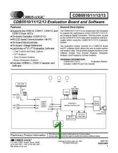
CDB5510/11/12/13
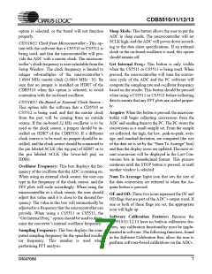
ically 5ppm/°C). By setting HDR3’s jumper to the
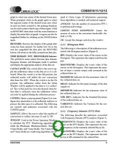
“REF” position, the user can supply an external
2) The 32 kHz on-board oscillator circuit (shown in
Figure 11) can be used by connecting HDR7 on the
voltage reference to J1’s REF input. V- is also pro- CDB5510 board and selecting the “On-board or ex-
vided at connector J1 to allow an easy connection ternal clock source” option in the software. The
to the negative supply. (Application Note 4 on Cir- DIP switches on the evaluation board should be set
rus Logic’s web site details various voltage refer- as shown in the “CS5510/12 External Clock” sec-
ences).
tion of Table 3.
Reference
Description
HDR3
3) An external clock can be provided by the user,
and connected to the SCLK post on HDR7. The
“On-board or external clock source” option in the
software should be selected when using an external
clock source, and the DIP switches on the evalua-
tion board should be set as shown in the
“CS5510/12 External Clock” section of Table 3.
V+
LT1019
REF
O
O
O
O VREF
O VREF
O VREF
Selects Analog
Power Supply
V+
Selects on board
V+
O
O
O
O VREF
O VREF
O VREF
LT1019 LT1019Reference LT1019
REF
(5ppm/°C)
Selects external
EXTERNAL reference source LT1019
The CS5511 and CS5513 include an internal oscil-
lator, and as such, need no external oscillator to
run. When using the CS5511 or CS5513, HDR7 on
the CDB5510 board should be left disconnected,
and the “CS5511/13 Internally Clocked” option
should be selected in the software. Likewise, the
V+
O
O
O
O VREF
O VREF
O VREF
REF
connected to J1
Table 2. Voltage Reference Selection Using HDR3
1.5 Clocking Options
The CS5510/11/12/13 are very simple ADCs, in-
tended to continuously convert and output data
when not in sleep mode. The CS5510 and CS5512
require an external clock signal on the SCLK input
pin to run properly. The CDB5510 evaluation
board provides three options for this clock source:
Eval Board Mode
SW1 Settings
CS5511/13 Internally Clocked
X is OPEN
A is OPEN
1
2
3
B is OPEN
OPEN
X
A
B
CS5510/12 Clock From 8515
X is OPEN
A is CLOSED
1
2
3
1) The microcontroller can be used to generate a
clock for the CS5510/12. The microcontroller’s
clock can be selected by removing the jumper from
HDR7 on the CDB5510 board, and selecting the
“CS5510/12 Clock from microcontroller” option in
the software. The DIP switches on the evaluation
board should be set as shown in the “CS5510/12
Clock from 8515” section of Table 3. The clock
frequency can be selected by changing the “Oscil-
lator Frequency” box in the software. Note that the
frequency options are limited by the microcontrol-
ler’s counter/timer circuitry, which divides the
3.6864 MHz clock by integer values to produce the
clock output.
B is CLOSED
OPEN
X
A
B
CS5510/12 External Clock
X is OPEN
A is OPEN
1
2
3
B is CLOSED
OPEN
X
A
B
RS-232 Test Mode
X is CLOSED
A is CLOSED
B is CLOSED
1
2
3
OPEN
X
A
B
Table 3. DIP Switch Settings
4
DS337DB2

 CIRRUS [ CIRRUS LOGIC ]