CAT1320, CAT1321
Advance Information
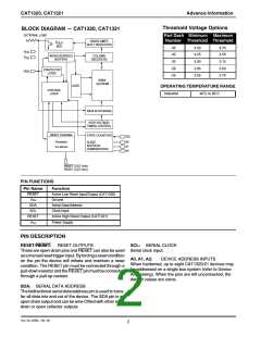
DEVICE OPERATION
Reset Controller Description
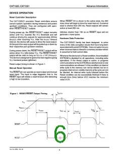
When RESET I/O is driven to the active state, the 200
msec timer will begin to time the reset interval. If external
reset is shorter than 200 ms, Reset outputs will remain
active at least 200 ms.
The CAT1320/21 precision Reset controllers ensure
correct system operation during brownout and power
up/down conditions. They are configured with open-
drain RESET/RESET outputs.
Glitches shorter than 100 ns on RESET input will not
generate a reset pulse.
During power-up, the RESET/RESET output remains
active until VCC reaches the VTH threshold and will
continue driving the outputs for approximately 200ms
(tPURST) after reaching VTH. After the tPURST timeout
interval, the device will cease to drive the reset output.
At this point the reset output will be pulled up or down by
their respective pull up/down resistors.
Hardware Data Protection
The CAT1320/21 family has been designed to solve
many of the data corruption issues that have long been
associatedwithserialEEPROMs. Datacorruptionoccurs
when incorrect data is stored in a memory location which
is assumed to hold correct data.
During power-down, the RESET/RESET output will be
active when VCC falls below VTH. The RESET/RESET
output will be valid so long as VCC is >1.0V (VRVALID).
The device is designed to ignore the fast negative going
VCC transient pulses (glitches).
WheneverthedeviceisinaResetcondition,theembedded
EEPROM is disabled for all operations, including write
operations. If the Reset output is active, in progress
communicationstotheEEPROMareabortedandnonew
communications are allowed. In this condition an internal
write cycle to the memory can not be started, but an in
progressinternalnon-volatilememorywritecyclecannot
be aborted. An internal write cycle initiated before the
Reset condition can be successfully finished if there is
enough time (5ms) before VCC reaches the minimum
value of 2V.
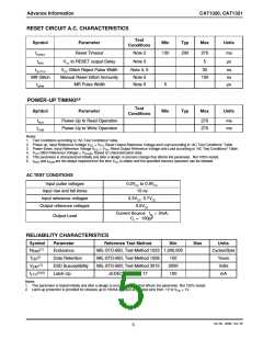
Reset output timing is shown in Figure 1.
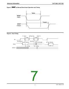
Manual Reset Operation
The RESET pin can operate as reset output and manual
reset input. The input is edge triggered; that is, the
RESET input will initiate a reset timeout after detecting
a high to low transition.
t
GLITCH
Figure 1. RESET/RESET Output Timing
V
TH
V
RVALID
t
RPD
t
V
t
PURST
CC
t
RPD
PURST
RESET
RESET
Doc. No. 25085, Rev. 00
6

 CATALYST [ CATALYST SEMICONDUCTOR ]