|
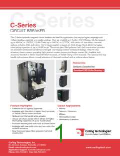
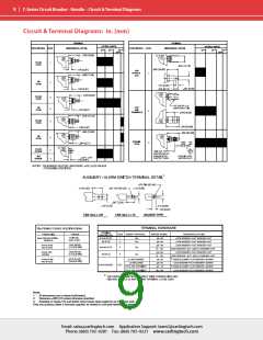
C-Series Circuit Breaker – General Specifications
2
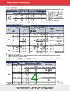
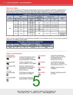
Electrical
Maximum Voltage
Mechanical
Endurance
AC, 480 WYE/277 VAC, 50/60 Hz
(see Table A.)
UL489: AC,240 VAC. (See Table D),
50/60 Hz, 125 VDC
Standard current coils: 0.100,
0.250, 0.500, 0.750, 1.00, 2.50,
5.00, 7.50, 10.0, 15.0, 25.0, 30.0,
35.0, 40.0, 50.0, 60.0, 70.0, 80.0,
90.0 and 100 amps. Other ratings
available, see Ordering Scheme.
10,000 ON-OFF operations @ 6 per
minute; with rated current &
voltage.
Trip Free
All C-Series circuit breakers will trip
on overload, even when actuator is
forcibly held in the ON position.
The operating actuator moves
positively to the OFF position when
an overload causes the breaker to
trip. With mid-trip, handle moves to
the mid position on electrical trip of
the circuit breaker. With mid trip
handle with alarm switch, handle
moves to the mid position and the
alarm switch actuates when the
circuit breaker is electrically
tripped.
Current Rating
Trip Indication
Standard Voltage Coils DC - 6V, 12V; AC - 120V; other
ratings available, see Ordering
Scheme.
Auxiliary Switch Rating SPDT; 10.1 amps-250VAC, DC Aux.
Switch 1.0A, 65 VDC. 0.5A,
80VDC,1/4 HP, 125VAC,VDE & TUV
1.0 125 VAC.
Insulation Resistance
Dielectric Strength
Minimum of 100 Megohms at 500
VDC.
Physical
UL, CSA: 1960 V 50/60 Hz for one
minute between all electrically
isolated terminals. C-Series Circuit
Breakers comply with the 8mm
spacing and 3750V 50/60 Hz
dielectric requirements from
hazardous voltage to operator
accessible surfaces, between
adjacent poles and from main
circuits to auxiliary circuits per
Publications EN 60950 and
VDE 0805.
Number of Poles
1-6 poles ≤ 50A; 1-4 poles @ 51-
70A; 1-2 poles 71-100A. UL489
Handle: 1 pole ≤ 100A, 2 pole ≤
50A; Rocker: 1 pole ≤ 100A.
Internal Circuit Config. Series (with or without auxiliary
switch, mid trip & mid trip with
alarm switch) Shunt & Relay with
current or voltage trip coils, Dual
Coil, Switch Only (with or without
aux. switch). UL489: Series (with or
without auxiliary switch, mid-trip &
midtrip with alarm switch).
Resistance, Impedance Values from Line to Load Terminal -
based on Series Trip Circuit
Weight
Standard Colors
Approx.112 grams/pole ( 3.95 oz).
Housing: Black
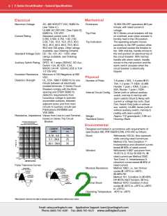
RESISTANCE, IMPEDANCE VALUES
Breaker.
from Line to Load Terminals
(Values Based on Series Trip Circuit Breaker)
Environmental
1000
CURRENT
(AMPS)
TOLERANCE
(%)
Designed and tested in accordance with requirements of
100
10
specification MIL-PRF-55629 & MIL-STD-202 as follows:
0.10 - 5.0
5.1 - 20.0
20.1 - 50.0
15
25
35
Shock
Withstands 100 Gs, 6ms sawtooth
while carrying rated current per
Method 213, Test Condition “I”.
Instantaneous and ultrashort curves
tested @ 90% of rated current.
Withstands 0.060” excursion from
10-55 Hz & 10 Gs 55-500 Hz, @
rated current per Method 204C,
Test Cond. A. Instantaneous &
ultrashort curves tested @ 90% of
rated current.
Method 106D, i.e., ten 24-hour
cycles @ +25°C to +65°C,
80-98% RH.
Method 101, Condition A (90-95%
RH @ 5% NaCl Solution, 96 hrs).
Method 107D, Condition A (five
cycles @ -55°C to +25°C to +85°C
to +25°C).
O
H
M
S
1
0.1
0.01
Vibration
0.001
0.01
0.1
1
10
100
AMPERE RATING
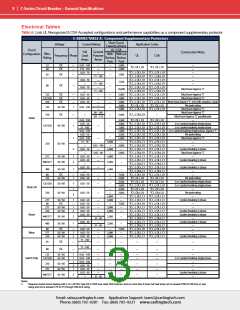
Pulse Tolerance Curves
60 Hz 1/2 Cycle
Inrush Pulse Tolerance
50 Hz 1/2 Cycle
Moisture Resistance
Inrush Pulse Tolerance
I
I
r
r
Time Delay Curves
Time Delay Curves
42, 44
& 46
22x
10x
42, 44
& 46
(50 Amps Max.)
(50 Amps Max.)
25x
12x
Time Delay Curves
Time Delay Curves
22, 24 (100 Amps Max.)
26 (70 Amps Max.)
22, 24 (100 Amps Max.)
26 (70 Amps Max.)
Salt Spray
t
t
10.0
20.0
5.0
8.33
16.67
4.165
Time in
Milliseconds
Thermal Shock
Operating Temperature -40°C to +85°C
*Manufacturer reserves the right to change product specification without prior notice.
Email: sales@carlingtech.com Application Support: team2@carlingtech.com
Phone: (860) 793–9281 Fax: (860) 793–9231 www.carlingtech.com

 Carling Technologies [ Carling Technologies ]