|
8
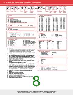
C-Series Circuit Breaker - Handle UL489 Listed – Ordering Scheme
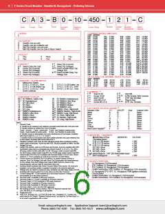
C A 3 B 0 14 450 1 2 1 K G
8
9
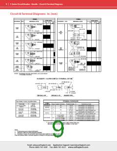
10
Mounting/
Barriers
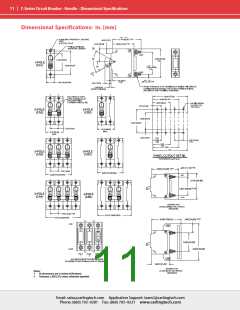
11
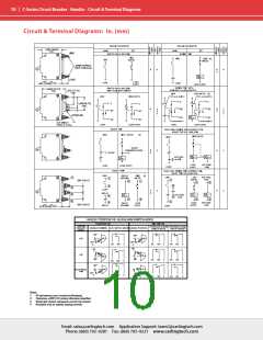
12
1
2
3
4
5
6
7
Terminal
Actuator
Color
Max. App. Agency
Rating Approval
Series
Actuator
Poles
Circuit
Aux/Alarm
Switch
Frequency
& Delay
Current Rating
1 SERIES
C
7 CURRENT RATING (AMPERES)
CODE AMPERES
210 0.100
215 0.150
220 0.200
225 0.250
230 0.300
235 0.350
240 0.400
245 0.450
250 0.500
255 0.550
260 0.600
265 0.650
270 0.700
275 0.750
280 0.800
285 0.850
290 0.900
295 0.950
410 1.000
512 1.250
415 1.500
517 1.750
420 2.000
522 2.250
425 2.500
527 2.750
430 3.000
435 3.500
440 4.000
445 4.500
450 5.000
455 5.500
460 6.000
465 6.500
470 7.000
475 7.500
480 8.000
485 8.500
490 9.000
495 9.500
610 10.000
710 10.500
611 11.000
711 11.500
612 12.000
712 12.500
613 13.000
614 14.000
615 15.000
616 16.000
617 17.000
618 18.000
620 20.000
622 22.000
624 24.000
625 25.000
630 30.000
635 35.000
640 40.000
660 60.000
670 70.000
680 80.000
685 85.000
690 90.000
695 95.000
810 100.00
1
2 ACTUATOR
A
B
S
T
Handle, one per pole
Handle, one per multipole unit
Mid-Trip Handle, one per pole
Mid-Trip Handle, one per pole & Alarm Switch
2
3 POLES
One
1
2
Two
3
Three
4 CIRCUIT
Series Trip (Current)
B
3
5 AUXILIARY / ALARM SWITCH
0
2
3
4
without Aux Switch
6
8 TERMINAL
S.P.D.T., 0.110 Q.C. Term.
S.P.D.T., 0.139 Solder Lug
S.P.D.T., 0.110 Q.C. Term.
(Gold Contacts)
6
8
9
S.P.S.T., 0.139 Solder Lug
S.P.S.T., 0.187 Q.C. Term.
S.P.D.T., 0.187 Q.C. Term.
7
9
9
10
1
2
3
4
5
Stud 10-32
Screw 10-32
Stud 1/4-20
Stud M5 x 0.8
Screw M5 x 0.8
6
Stud M6
8
9
8
8
9
7/16” Clip Terminal
A
C
Plug-In Stud
5/16” Clip Terminal
8
6 FREQUENCY & DELAY
11 DC Ultra Short
12 DC Short
26 50/60Hz Long
11
9 ACTUATOR COLOR & LEGEND
4
42 50/60Hz Short, High-inrush
Actuator Color
White
ON-OFF
Dual
Legend Color
Black
4
4
4
4
14 DC Medium
44 50/60Hz Medium, High-inrush
B
D
G
J
1
2
3
4
5
6
7
8
16 DC Long
46 50/60Hz Long, High-inrush
Black
White
21 50/60Hz Ultra Short
22 50/60Hz Short
24 50/60Hz Medium
52 DC Short, High-inrush
Red
White
54 DC Medium, High-inrush
Green
Blue
Yellow
Gray
White
4
56 DC Long, High-inrush
L
White
N
Q
S
Black
Black
Notes:
1
Actuator Code:
Orange
Black
A: Handle tie pin spacer(s) and retainers provided assembled with multi-pole units.
B: Handle located, as viewed from front of breaker in left pole. 2 pole maximum.
S: Handle moves to mid-position only upon electrical trip of the breaker.
T: Handle moves to mid-position and alarm switch activates only upon electrical trip
of the breaker.
Standard multipole units have all poles identical except when specifying auxiliary
switch and/or mixed poles.
2 & 3 pole circuit breakers required for 120/240 VAC (Maximum application rating
code C) applications, have all poles identical except when specifying auxiliary /
alarm switch which is normally supplied in extreme right pole per figure B. Terminal
barriers are required on all multipole breakers.
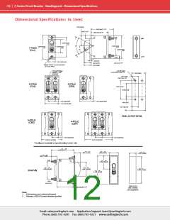
10 MOUNTING / BARRIERS
MOUNTING STYLE
12
BARRIERS
Threaded Insert
2
1
2
6-32 x 0.195 inches
ISO M3 x 5mm
yes
yes
11 MAXIMUM APPLICATION RATING
B
C
D
K
F
125 DC
120/240 AC
240 AC
120 AC
277 AC
80 DC
Third pole is for 120/240 VAC applications requiring neutral disconnect. The 3rd
pole has the same construction as poles 1 & 2.
On multi-pole breakers, one auxiliary. switch is supplied, mounted in the extreme
right pole.
2
3
VDE approval on auxiliary switch codes 2, 3 & 4 only.
Auxiliary / Alarm Switch with Independent Circuit ie: separate from breaker circuit,
only available with circuit breakers rated 50 amp maximum at 80 VDC, 125 VDC,
and 120 VAC. Auxiliary / Alarm Switch with Dependent Circuit ie: same as circuit
breaker, is supplied from factory with common terminal of auxiliary / alarm switch
connected to line terminal on 120/240 and 240 VAC ratings. Circuit breakers rated
120 VAC 50 amp maximum can be supplied with Auxiliary/Alarm switch common
terminal connected to breaker line terminal. Consult factory for special catalog
number.
M
11
12 AGENCY APPROVAL
A
F
G
J
without approvals
UL489 Listed, CSA Certified & VDE Certified
UL489 Listed & CSA Certified
UL489 Listed, CSA Certified & TUV Certified
4
5
Available up to 50 amps maximum.
Current ratings 71 - 100 with VDE approvals are available up to two poles
maximum.
6
7
8
9
Terminal Codes 9 & C are not VDE approved.
Terminal Code 1 available to 60 amps maximum.
Terminal Codes 2, 4, 5 & C available to 50 amps maximum.
Terminal Codes 3, 6 & 9 available to 100 amps maximum.
10 Terminal Code A available to 100 amps maximum.
11 VDE and TUV approvals require Dual (I-O, ON-OFF) markings on all handles.
12 Barriers supplied on multi-pole units only.
Email: sales@carlingtech.com Application Support: team2@carlingtech.com
Phone: (860) 793–9281 Fax: (860) 793–9231 www.carlingtech.com

 Carling Technologies [ Carling Technologies ]