Preliminary Datasheet
BOOST CONTROLLER
AP3039
Pin Description (Continued)
Pin Number
Pin Name
Function
An external soft start time capacitor is connected from this pin to ground and is charged by
internal 12μA current source to control regulator soft start time
14
SS
Two resistors connected from this pin to ground and the VIN pin respectively to set start up
and shutdown level
15
16
UVLO
OV
Over output voltage protection pin
Exposed backside pad. Solder to the circuit board ground plane with sufficient copper
connection to ensure low thermal resistance
EP
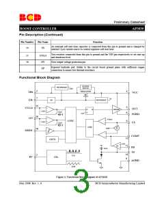
Functional Block Diagram
BYPASS
SWITCH
REFERENCE
1.25V
2
1
4
REGULATOR
VIN
EN
VCC
3V
REFERENCE
EN
15
16
5
6
UVLO
OUT
Q
DRIVER
R
1.25V
1.25V
22μA
22μA
S
CLK
PGND
OV
110mV
LOGIC
8
CS
+
+
LEB
SAW
Σ
10
SHDN
COMP
13
OSTD
0.6V11
EA
FB
SS
12μA
14
9
7
CLK
RT
OSL
AGND
SAW
Figure 3. Functional Block Diagram of AP3039
BCD Semiconductor Manufacturing Limited
May 2008 Rev. 1. 0
3

 BCDSEMI [ BCD SEMICONDUCTOR MANUFACTURING LIMITED ]