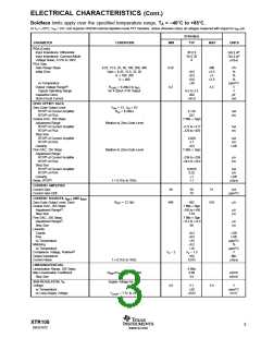
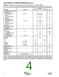
ELECTRICAL CHARACTERISTICS (Cont.)
Boldface limits apply over the specified temperature range, TA = –40°C to +85°C.
At TA = +25°C, VPS = 24V, and Supertex DN2540 external depletion-mode FET transistor, unless otherwise noted, all voltages measured with respect to IRET pin.
XTR108EA
PARAMETER
CONDITIONS
MIN
TYP
MAX
UNITS
PGA (Cont.)
Input Impedance: Differential
Input Impedance: Common-Mode
Voltage Noise, 0.1Hz to 10Hz
PGA Gain
30 || 6
50 || 20
6
GΩ || pF
GΩ || pF
µVp-p
Gain Range Steps
Initial Error
6.25, 12.5, 25, 50, 100, 200, 400
Gain = 6.25, 12.5, 25, 50
G = 100, 200
6.25
0.2
400
±2.5
±3
V/V
%
%
%
ppm/°C
V
±0.5
±0.5
±0.8
±30
G = 400
±3.5
vs Temperature
Output Voltage Range(5)
Typical Operating Range
Capacitive Drive
RLOAD = 6.34kΩ to IRET
for 4-20mA XTR Output
4.5
0.5 to 2.5
200
V
pF
Short-Circuit Current
+6/–9
mA
ZERO OFFSET DACS
Zero-Code Output Level
RTO(6) of Current Amplifier
RTO(6) of PGA
VCM = 1V, VIN = 0V
RV/I = 6.34kΩ
4.116
522
mA
mV
Coarse DAC, 256 Steps
Adjustment Range
RTO(6) of Current Amplifier
RTO(6) of PGA
7 Bits + Sign
Relative to Zero-Code Level
–3.77 to +3.77
–470 to +470
mA
mV
Step Size
RTO(6) of Current Amplifier
RTO(6) of PGA
0.029
3.7
mA
mV
Linearity
±0.5
LSB
Fine DAC, 256 Steps
Adjustment Range
RTO(6) of Current Amplifier
RTO(6) of PGA
Relative to Zero-Code Level
7 Bits + Sign
–236 to +236
–29.4 to +29.4
µA
mV
Step Size
RTO(6) of Current Amplifier
RTO(6) of PGA
Linearity
Noise, RTO(6)
0.0018
0.23
±1
mA
mV
LSB
µAp-p
f = 0.1Hz to 10Hz
1.1
CURRENT AMPLIFIER
Current Gain
Current Gain Drift
49
50
10
51
A/A
ppm/°C
CURRENT SOURCES, IREF1 AND IREF2
Zero-Code Output Level, Each
Coarse DAC, 256 Steps
Adjustment Range(7)
Step Size
RSET = 12.1kΩ
480
493
510
µA
7 Bits + Sign
–195 to +195
1.54
µA
µA
Fine DAC, 256 Steps
Adjustment Range(7)
Step Size
7 Bits + Sign
–12.2 to +12.2
96
µA
nA
Linearity
Coarse
Fine
±0.2
±0.5
LSB
LSB
vs Temperature
Matching
±35
±0.2
ppm/°C
%
vs Temperature
±10
VS – 1.5
100
ppm/°C
V
MΩ
Compliance Voltage, Positive(5)
Output Impedance
Current Noise
VS – 2
f = 0.1Hz to 10Hz
0.015
µAp-p
LINEARIZATION DAC
Linearization Range, 256 Steps
Max Linearization Coefficient
Step Size
8 Bits
0.99
3.9
∆IREF/∆VIN, RLIN = 15.8kΩ
µA/mV
nA/mV
SUB-REGULATOR, VS
Voltage
vs Temperature
Supply Voltage for XTR
4.8
5.1
±50
±0.03
5.4
V
ppm/°C
mV/V
vs Loop-Supply Voltage
VLOOP = 7.5V to 24V
XTR108
SBOS187C
3
www.ti.com

 BB [ BURR-BROWN CORPORATION ]