PCM1753
PCM1754
PCM1755
SLES092A – OCTOBER 2003 – REVISED AUGUST 2004
www.ti.com
SYSTEM CLOCK AND RESET FUNCTIONS
System Clock Input
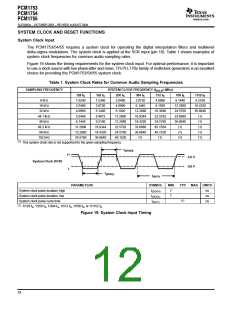
The PCM1753/54/55 requires a system clock for operating the digital interpolation filters and multilevel
delta-sigma modulators. The system clock is applied at the SCK input (pin 16). Table 1 shows examples of
system clock frequencies for common audio sampling rates.
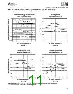
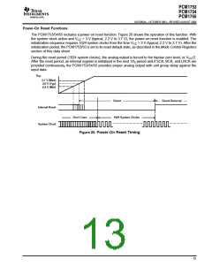
Figure 19 shows the timing requirements for the system clock input. For optimal performance, it is important
to use a clock source with low phase-jitter and noise. TI’s PLL170x family of multiclock generators is an excellent
choice for providing the PCM1753/54/55 system clock.
Table 1. System Clock Rates for Common Audio Sampling Frequencies
SAMPLING FREQUENCY
SYSTEM CLOCK FREQUENCY (f ) (MHz)
SCLK
128 f
192 f
256 f
384 f
512 f
768 f
1152 f
S
S
S
S
S
S
S
8 kHz
16 kHz
32 kHz
44.1 kHz
48 kHz
88.2 kHz
96 kHz
192 kHz
1.0240
2.0480
4.0960
5.6448
6.1440
11.2896
12.2880
24.5760
1.5360
3.0720
6.1440
8.4672
9.2160
16.9344
18.4320
36.8640
2.0480
4.0960
3.0720
6.1440
12.2880
16.9344
18.4320
33.8688
36.8640
(1)
4.0960
8.1920
16.3840
22.5792
24.5760
45.1584
49.1520
(1)
6.1440
12.2880
24.5760
33.8688
36.8640
(1)
9.2160
18.4320
36.8640
(1)
8.1920
11.2896
12.2880
22.5792
24.5760
49.1520
(1)
(1)
(1)
(1)
(1)
(1)
(1)
This system clock rate is not supported for the given sampling frequency.
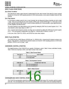
t
(SCKH)
H
2.0 V
0.8 V
System Clock (SCK)
L
t
(SCKL)
t
(SCY)
PARAMETERS
SYMBOL
MIN
7
TYP
MAX UNITS
System clock pulse duration, high
t
ns
ns
ns
(SCKH)
System clock pulse duration, low
System clock pulse cycle time
t
7
(SCKL)
(1)
t
(SCY)
(1)
1/128 f , 1/256 f , 1/384 f , 1/512 f , 1/768 f , or 1/1152 f
S
S
S
S
S
S
Figure 19. System Clock Input Timing
12

 BB [ BURR-BROWN CORPORATION ]