SYSTEM CLOCK OUTPUT
SYSTEM CLOCK AND RESET
FUNCTIONS
A buffered version of the system clock input is available at
the SCLKO output (pin 39). SCLKO can operate at either
full (fSCLKI) or half (fSCLKI/2) rate. The SCLKO output
frequency may be programmed using the CLKD bit of
Control Register 9. The SCLKO output pin can also be
enabled or disabled using the CLKE bit of Control Register
9. The default is SCLKO enabled.
SYSTEM CLOCK INPUT
The PCM1600 and PCM1601 require a system clock for
operating the digital interpolation filters and multi-level
delta-sigma modulators. The system clock is applied at the
SCLKI input (pin 38). For sampling rates from 10kHz
through 64kHz, the system clock frequency may be 256,
384, 512, or 768 times the sampling frequency, fS. For
sampling rates above 64kHz, the system clock frequency
may be 256, 384, or 512 times the sampling frequency.
Table I shows examples of system clock frequencies for
common audio sampling rates.
POWER-ON AND EXTERNAL RESET FUNCTIONS
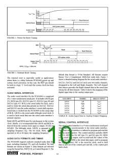
The PCM1600 includes a power-on reset function. Figure 2
shows the operation of this function.
The system clock input at SCLKI should be active for at
least one clock period prior to VDD = 2.0V. With the system
clock active and VDD > 2.0V, the power-on reset function
will be enabled. The initialization sequence requires 1024
system clocks from the time VDD > 2.0V. After the initial-
ization period, the PCM1600 will be set to its reset default
state, as described in the Mode Control Register section of
this data sheet.
Figure 1 shows the timing requirements for the system clock
input. For optimal performance, it is important to use a clock
source with low phase jitter and noise. Burr-Brown’s
PLL1700 multi-clock generator is an excellent choice for
providing the PCM1600 system clock source.
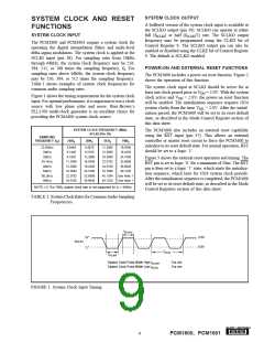
SYSTEM CLOCK FREQUENCY (MHz)
SCLKI (Pin 38)
SAMPLING
The PCM1600 also includes an external reset capability
using the RST input (pin 37). This allows an external
controller or master reset circuit to force the PCM1600 to
initialize to its reset default state. For normal operation, RST
should be set to a logic ‘1’.
FREQUENCY (fS)
256fS
384fS
512fS
768fS
22.05kHz
24kHz
5.6448
6.1440
8.4670
9.2160
11.2896
12.2880
16.3840
22.5792
24.5760
32.7680
45.1584
49.1520
16.9340
18.4320
32kHz
8.1920
12.2880
16.9340
18.4320
24.5760
33.8688
36.8640
24.5760
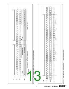
Figure 3 shows the external reset operation and timing. The
RST pin is set to logic ‘0’ for a minimum of 20ns. The RST
pin is then set to a logic ‘1’ state, which starts the initializa-
tion sequence, which lasts for 1024 system clock periods.
After the initialization sequence is completed, the PCM1600
will be set to its reset default state, as described in the Mode
Control Registers section of this data sheet.
44.1kHz
48kHz
11.2896
12.2880
16.3840
22.5792
24.5760
33.8688
36.8640
64kHz
49.1520
88.2kHz
96kHz
See Note 1
See Note 1
NOTE: (1) The 768fS system clock rate is not supported for fS > 64kHz.
TABLE I. System Clock Rates for Common Audio Sampling
Frequencies.
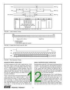
tSCLKIH
2.0V
“H”
SCLKI
0.8V
“L”
fSCLKI
tSCLKIH
System Clock Pulse Width High tSCLKIH
System Clock Pulse Width Low tSCLKIL
: 7ns min
: 7ns min
FIGURE 1. System Clock Input Timing.
®
9
PCM1600, PCM1601

 BB [ BURR-BROWN CORPORATION ]