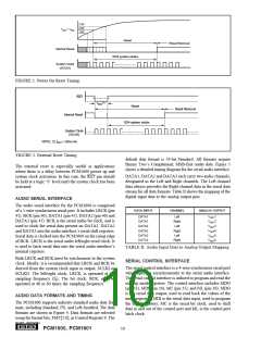
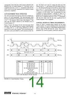
2.4V
2.0V
1.6V
VCC = VDD
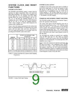
Reset
Reset Removal
Internal Reset
1024 system clocks
System Clock
(SCLKI)
FIGURE 2. Power-On Reset Timing.
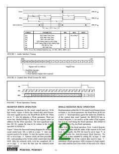
RST
(1)
tRST
Reset
Reset Removal
Internal Reset
1024 system clocks
System Clock
(SCLKI)
NOTE: (1) tRST = 20ns min.
FIGURE 3. External Reset Timing.
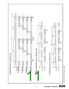
default data format is 24-bit Standard. All formats require
Binary Two’s Complement, MSB-first audio data. Figure 5
shows a detailed timing diagram for the serial audio interface.
The external reset is especially useful in applications
where there is a delay between PCM1600 power up and
system clock activation. In this case, the RST pin should
be held at a logic ‘0’ level until the system clock has been
activated.
DATA1, DATA2 and DATA3 each carry two audio channels,
designated as the Left and Right channels. The Left channel
data always precedes the Right channel data in the serial data
stream for all data formats. Table II shows the mapping of the
digital input data to the analog output pins.
AUDIO SERIAL INTERFACE
The audio serial interface for the PCM1600 is comprised
of a 5-wire synchronous serial port. It includes LRCK (pin
41), BCK (pin 40), DATA1 (pin 45), DATA2 (pin 46) and
DATA3 (pin 47). BCK is the serial audio bit clock, and is
used to clock the serial data present on DATA1, DATA2
and DATA3 into the audio interface’s serial shift registers.
Serial data is clocked into the PCM1600 on the rising edge
of BCK. LRCK is the serial audio left/right word clock. It
is used to latch serial data into the serial audio interface’s
internal registers.
DATA INPUT
CHANNEL
ANALOG OUTPUT
DATA1
DATA1
DATA2
DATA2
DATA3
DATA3
Left
Right
Left
VOUT1
VOUT2
VOUT3
VOUT4
VOUT5
Right
Left
Right
VOUT6
TABLE II. Audio Input Data to Analog Output Mapping.
Both LRCK and BCK must be synchronous to the system
clock. Ideally, it is recommended that LRCK and BCK be
derived from the system clock input or output, SCLKI or
SCLKO. The left/right clock, LRCK, is operated at the
sampling frequency (fS). The bit clock, BCK, may be
operated at 48 or 64 times the sampling frequency.
SERIAL CONTROL INTERFACE
The serial control interface is a 4-wire synchronous serial port
which operates asynchronously to the serial audio interface.
The serial control interface is utilized to program and read the
on-chip mode registers. The control interface includes MDO
(pin 33), MDI (pin 34), MC (pin 35), and ML (pin 36). MDO
is the serial data output, used to read back the values of the
mode registers; MDI is the serial data input, used to program
the mode registers; MC is the serial bit clock, used to shift
data in and out of the control port and ML is the control port
latch clock.
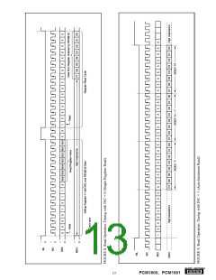
AUDIO DATA FORMATS AND TIMING
The PCM1600 supports industry-standard audio data for-
mats, including Standard, I2S, and Left-Justified. The data
formats are shown in Figure 4. Data formats are selected
using the format bits, FMT[2:0], in Control Register 9. The
®
10
PCM1600, PCM1601

 BB [ BURR-BROWN CORPORATION ]